
Connecting everything for your Arducopter
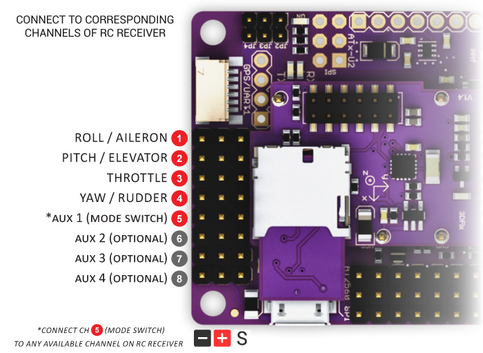
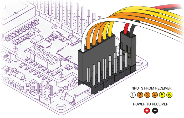
1. Connecting your motors and RC gearBefore you can configure your Arducopter, you will need to first connect everything together. This is quite easy. You need to connect your RC receiver to the Input side of the board. You can use the cables included with your Arducopter Kit, or if you are using another frame, you can use jumper cables, or female to female servo cables
|
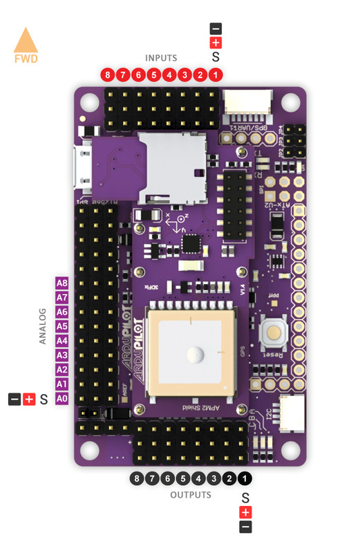
Ardupilot mega Pin numbering (click for image for larger version)
|
|
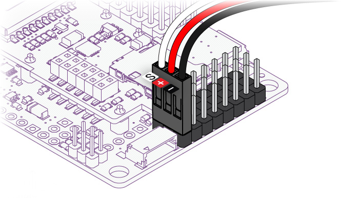
If you are using female to female servo cables, The ground (black) side of each connector must be on the outside for the board, the signal (white/orange) needs to be on the inside as shown below.
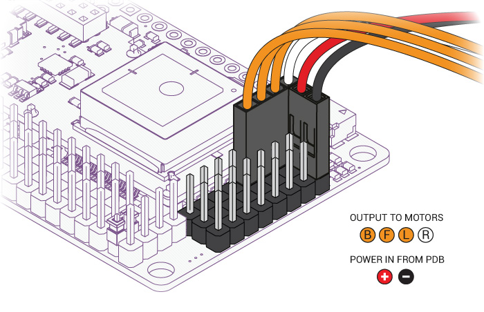
Please note, that your ESC, connectors should be plugged in the the output side, it is suggested that you only use power from one of your ESC's. This can be dune by cutting the red wire on all but one of the ESC's, or by using a special adaptor.
|
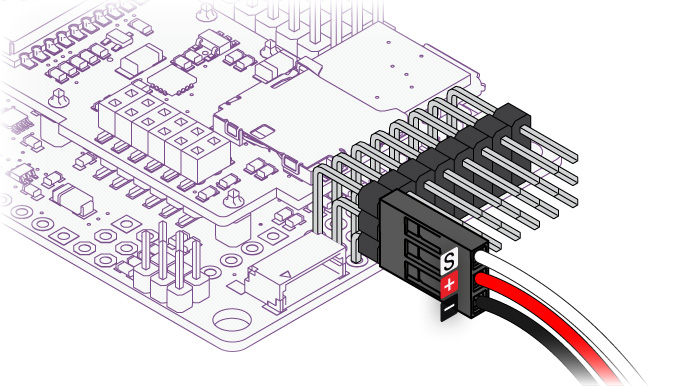
If you are using a multi-pin connector that was included with your Arducopter Kit, connect them as shown below
|
2. Connecting ArduCopter motors
|
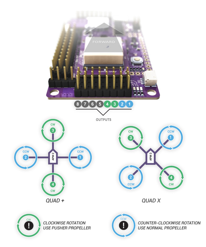
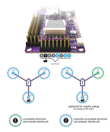
Once again if you are using an Arducopter Kit, with the PDB, then you dont need to worry about this if you soldered everything correctly as the motors are assigned to the correct pins with the cables you plugged connected in the previous step. However you will neet to make sure your motors are spinning in the correct direction. The images below show the possible arducopter configurations with correct motor orientation
|
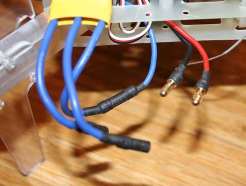
Quick Tip: If your motor is not spinning in the correct direction, simply switch the position of any two of the ESC-motor wires.
|
|
Arducopter Quad
|
Arducopter Tri
|
|
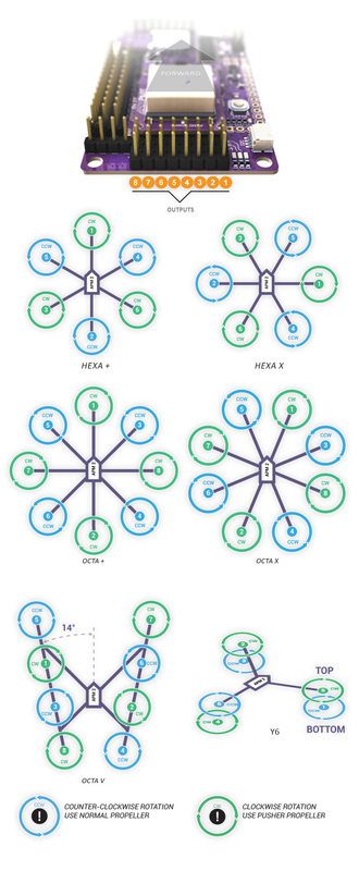
Arducopter Hexa, and Octa and Y6
|
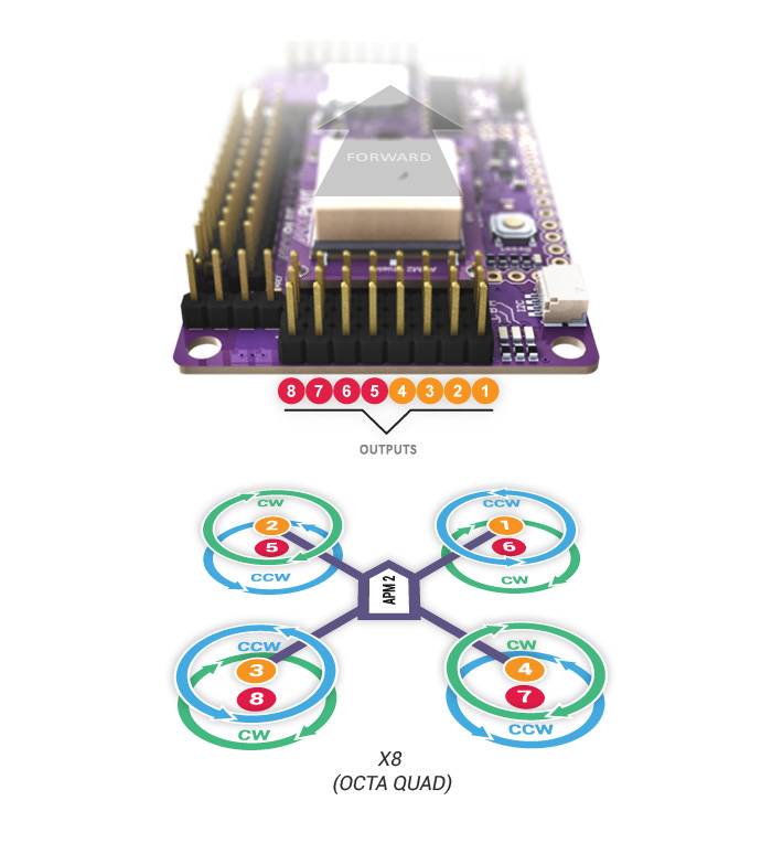
Arducopter OCTA QUAD (X8)
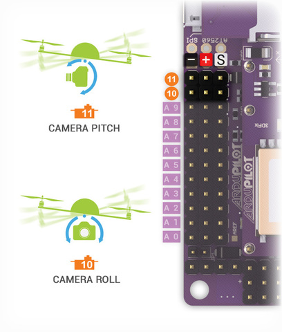
Connecting a Roll-Tilt Camera mount
|
3. Connecting Optional Sensors
|
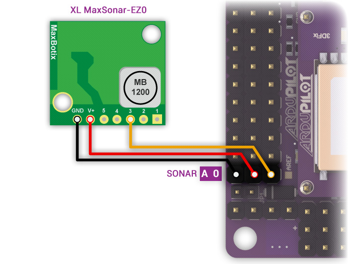
Sonar - Ultrasonic Rangefinder

AC2 supports the MaxSonar line of sonars for low level altitude hold and in the future collision avoidance. Below 10 meters sonar is primarily used for altitude hold. Above 10 meters, the barometric sensor is used. GPS is not required for altitude hold.
|
The sonar sensors are quite sensitive to noise, adding something like a ferrite choke to your cable could help. The most important is to mount your sonar away from other electronics like ESC, or wireless telemetry modules.
Possible Causes of sonar Interferance
|
|
|
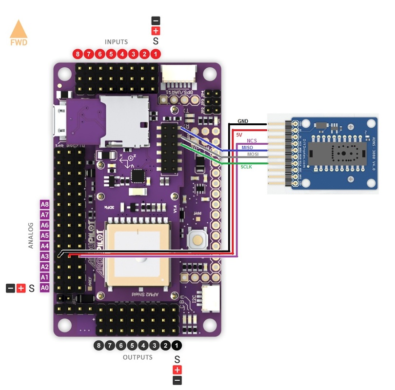
Optical Flow Sensor
The optical flow sensor is used to improve the position hold accuracy of your arducopter. This sensor is supported from Arducopter 2.6 and above.
|
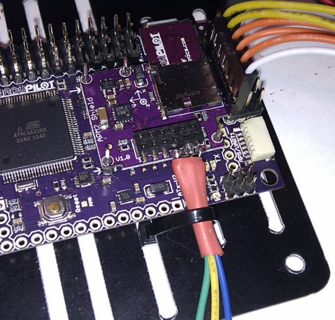
Connecting to APMv2
|
Now that everything has been connected everything the next thing to do is configure arducopter firmware for your frame.