Arduino based Arducopter UAV, the open source multi-rotor
  • Home
  • What do I need?
  • Where to buy?
  • Updates
  • IRIS Quadcopter UAV
    • Iris Manual >
      • Iris Introduction
      • Before you Fly
      • Flying
      • Advanced
      • Support
  • Have any Questions?
  • ArduCopter QuickStart
    • All Arducopter Guides

Configuring Arducopter

6/3/2012

4 Comments

 
Picture
This guide will show you how to configure the settings and calibrate arducopter so that you are ready for your first flight


Configuring Arducopter

Picture
Warning:  Before you configure your arducopter please make sure that you remove the PWM cable from your ArduPilot mega board.  This is for your own safety, if the motors start spinning by accident they can cause serious damage

When you connect the motors (for some testing functions/calibration please make sure you are alert and take the relevant precautions like removing the propellers.
Reset the board:  This just clears the EEPROM and otherwise ensures a clean setup. In Mission Planner click the Terminal tab, type 'setup' & hit Enter, then type 'erase'.  

First Time Setup

Picture
Click on the APM Setup button to run the first time setup
Picture
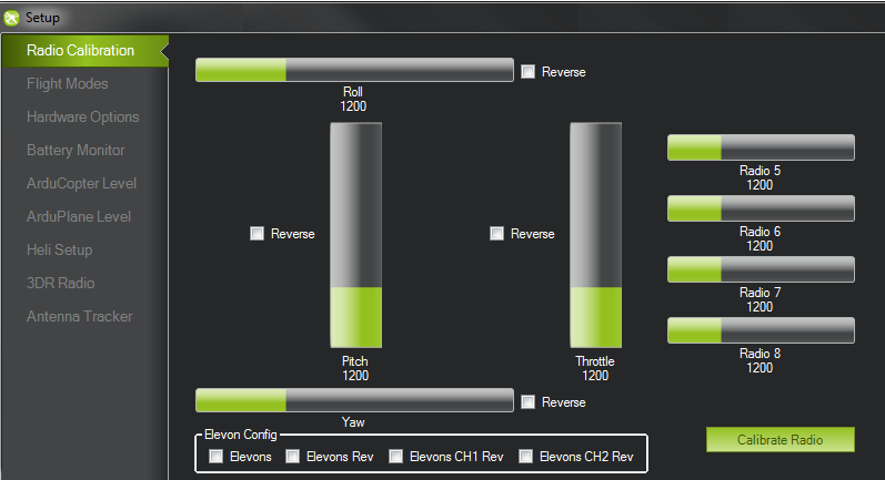
Once you click on the APM Setup button a new window will open, that will guide you through the set-up process
  • Once you have loaded the firmware onto your board and connected everything, the next step is to run the First time setup.  This is done with the mission planner that you installed earlier. 
  • On the mission planner make sure you have selected the correct COM port and baud rate 115200 (57600 if using xbee/radio modules).  The com port will usually be the highest number and should say arduino mega. 
  • Then you must go the the Firmware tab, and click on the APM setup button as shown in the image
  • Note: with APM 1 you MUST have a LiPo plugged in to your power distribution board to power your RC receiver. USB power does not power the RC receiver. If you do not separately power the RC system, APM will be unable to read any signals on its RC inputs and may freeze. With APM 2 this is not necessary.

1. Setup and Calibrate Radio Transmitter

Picture
Caution: This section assumes you have set up and programmed your RC transmitter and receiver correctly. This might be a good time to review the manual that came with your RC controller system. Pay special attention to the sections on:
  • Channel reversing and mixing
  • "expo" modes which change the responsiveness of your controls according to a curve
  • failsafe modes for signal loss. An RX that "remembers" the last throttle setting if it loses signal, will cause a plane to "coast", but will cause a heli or multi-rotor to continue climbing forever, rapidly so if you lost signal during an aggressive ascent. (this is known as "not good").
 
Instructions for setting up the WFT07 transmitter are can be found here

Please refer the your Radio Transmitter radio manual.  In general make sure your radio is set to Airplane/ fixed wing mode (helicopter mode uses mixing which is not required for Arducopter).   
Picture
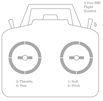
The First Tab will allow you to calibrate your radio transmitter with your arducopter
The first tab that will open will be the radio calibration screen.  Please make sure that your reciever has power (via APM), and your transmitter is on.  Make sure your radio is turned on and the receiver is connected to the ardupilot mega board.
When you move the sticks on your transmitter you should see the green bars move accordingly.  If they are not, please make sure your receiver has power.  If you notice that any channels are reversed, you can either tick the reverse button on the planner, or change the settings on your radio (suggested) 

Here is how the outputs should be setup for each channel:
  • CH 1: Roll Left = low PWM – Roll Right = High PWM
  • CH 2: Pitch Forward = low PWM – Pitch Back = High PWM
  • CH 3: Low Throttle = low PWM – High Throttle = High PWM
  • CH 4: Yaw Left = low PWM – Yaw Right = High PWM
  • CH 5: Flight Mode
  • CH 6: up to you
  • CH 7: not engaged = low PWM – engaged = High PWM

2. Choosing your Flight Modes

Picture
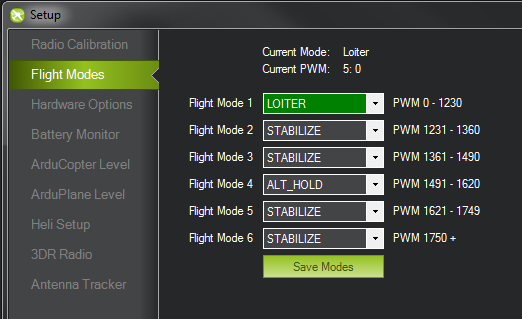
You can choose up to 6 flight modes with arducopter
You can choose different flight modes that you can change while you are flying with your RC transmitter (channel 5).  Some radios dont have a 6 position switch, so you may only be able to use 2 or 3 modes.  If you mix some channels you can use more flight modes.  Toggle your channel 5 switch to see which mode you are currently in (indicated by the green highlighted mode) 


Make sure that you have at least one mode as stabilise so you can take control of your arducopter if things are going wrong

3. Configure additional hardware

Picture
Hardware Options screen allows you to choose which extra sensors you are using
With Arducopter, you can use extra sensors like sonar, or an optical flow sensor.  This screen allows you to enable them.  Since the compass is build into Ardupilot mega v2, this is enabled and you will need to set the compass settings. 
Picture
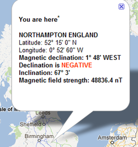
To manually enter a declination for your geographic location, you can find the correct value by clicking on the link to open a web browser. Enter your location and it will give you a declination, as shown above. For the example image, you would then enter a deglination of -1.48 in your mission planner.
For the magnetometer (compass), you have a choice of calibration options once you enable the sensor:
  1. You can do nothing, and the code will try to figure out all the offsets and declination by comparing the compass readings with the GPS and IMU readings over time in flight. Pro: No user effort. Con: It takes a few minutes of flying to get right, so the compass is inaccurate at first launch.
  2. Manual calibration in the Mission Planner. You can enter your Declination as instructed below and then press the "Live Calibration" button and move and rotate your aircraft around for 30 seconds while it records the data and does some math to calibrate the sensor. Pro: It works. Con: it's a little awkward, especially for big aircraft. Also it doesn't reflect the magnetic interference that can occur when the motors are going in flight.  Do it outside, away from metal  Ideally, do it while connected via wireless telemetry (3DR radios or Xbees). If you don't have that, you can do it while connected via USB, but you'll have to reverse direction with every step of the "calibration dance" or you'll get all wound up in your cable!
  1. Replay a flight log. This is a very cool option, shown above as Log Calibration, where you can just replay a previously recorded flight log (.tlog) and the code will compare the GPS and IMU readings with the compass reading and make the necessary corrections. Pro: Works great. Con: You must have already flown, if you load a .tlog file where you didn't actually fly you'll mess up your calibration and will have to do it again or risk poor flight performance.

4. Choosing Frame Orientation

Picture
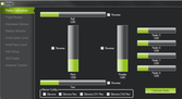
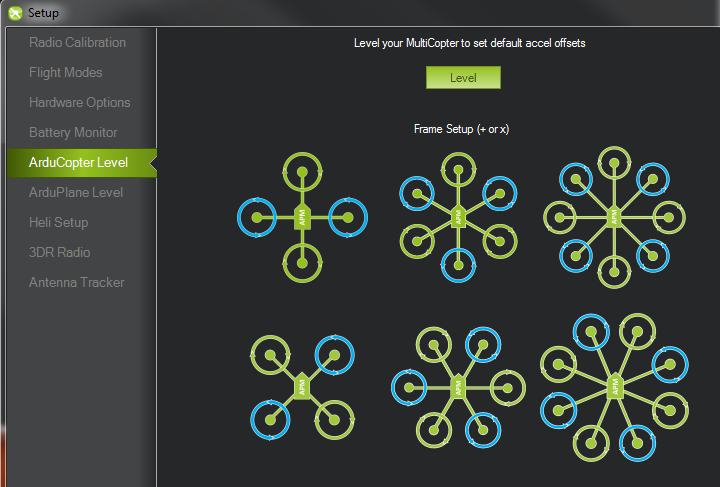
This screen is used to calibrate your sensors, and choose your frame configuration
This screen allows you to set your Arducopter orientation.  Before you start you must first Level your arudcopter.  Make your your arducopter is on a level surface, and click the Level button to calibrate the sensors.  Now you can choose between an X or + orientation of your frame by clicking on the image that is the same as your arducopter frame 

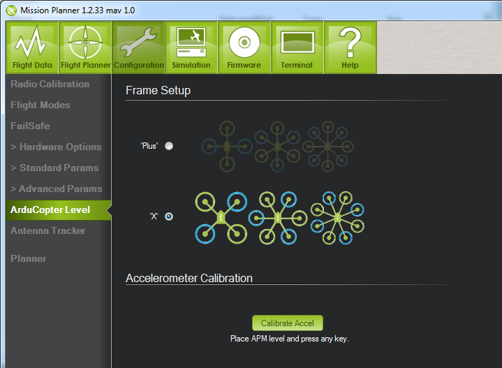
5. Calibrate the accelerometer (level arducopter)

Picture
  • Place your copter a level surface and press the "Calibrate Accel" button to begin the accelerometer calibration procedure
  • Follow the short instructions which appear just below the button which ask you to place the copter in 6 different orientations. Please be sure the copter does not move as you click the button during each step. Once you see the text "Done" on the button it is finished (don't press the "Done" button).
  • Note: the final accelerometer offsets and scaling are stored in the INS_ACOFFS_X, Y, Z and INS_ACCSCAL_X, Y, Z parameters. The values are board specific so you can complete this procedure before placing APM on the frame.
  • Note2: Except for the first step of the calibration process, it is not critical that the APM is held at exactly the angle requested. In fact, with the exception of the first position (level) even the order is not important, the calibration procedure just needs 6 points and it works best if they are as different as possible (thus the 6 positions all at 90degrees from each other). Keeping the board completely still at each step is important however.

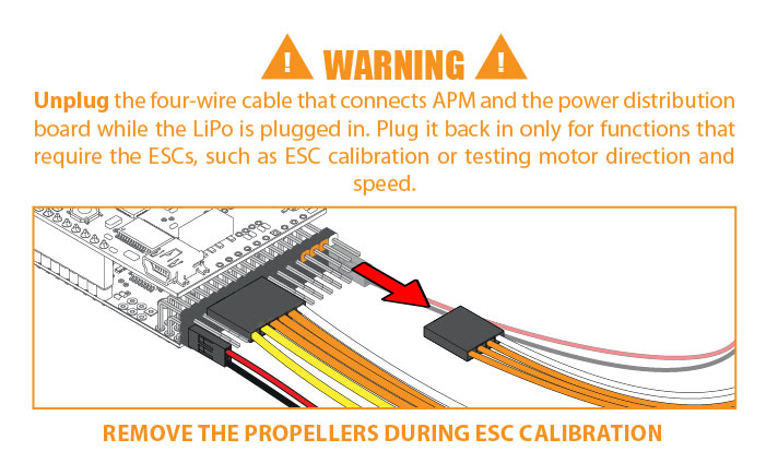
6. Calibrating your ESC

There are two ways to calibrating your ESC's for Arducopter.  An easy was and a longer, but better way. 
Automatic ESC calibration
This method works once you have all the ESCs connected to the power distribution board and have connected all your RC cables as instructed earlier in the manual and otherwise set up your quad. 

Safety First! - Remove the props!
  1. Disconnect USB
  2. Put the throttle high and connect the Lipo to power the APM
  3. When the APM boots the lights will cycle continuously
  4. Disconnect the Lipo and reconnect it. High PWM will be sent to the ESCs triggering calibration
  5. Drop your throttle stick to the lowest position. You should hear a confirmation/arming beep or two. Move the throttle to confirm all ESCs are armed and working in sync.
  6. Unplug the battery. Your ESCs are now calibrated. No further action is required.
Manual ESC calibration
Make sure your transmitter end points are set at +100%/-100% if using a programmable transmitter.

Safety First! Remove the prop from the motor you're calibrating.
  1. With NO BATTERY CONNECTED, plug the three-wire plug of the ESC you want to calibrate into the throttle channel of your RC receiver.
  2. Turn on your transmitter and push the throttle stick to full up.
  3. Plug the ESC into the LiPo battery
  4. You will hear a musical note and then 2 beeps. After the two beeps drop the throttle to full down. You will then hear a number of beeps (3 beeps for 3 cell LiPo, 4 for 4 cell, etc) and then a single longer beep indicating the end points have been set and the ESC is calibrated and ready to fly. You may now disconnect your LiPo.
  5. Repeat for the other three ESCs.
  6. If it appears that the ESC's did not calibrate then the throttle channel on the transmitter might need to be reversed
Once you have calibrated your ESCs, you can test your APM by turning it on (pluggin in the battery).  Once APM boots up, arm your ESCs by pushing the yaw stick all the way to the right for at least four seconds. You can then give a small amount of throttle (stand clear of the props!). All motors should spin about same speed and they should start same time. If not you may need to try re-calibrating your ESC. 
If you have any questions or comments please add them below or ask them on the forums
4 Comments
Gergo
1/29/2013 04:03:33 pm

Hi, I am Gergo, I am new to this forum. I am building an X quadcopter, considering to use the APM 2 autopilot and I am wondering if anyone has the experience and can tell me if this board supports a 'stretched X' type configuration, that is, where the rotors are placed in a rectangular arrangement instead of a square?

Thank you for your help in advance

Gergo

Reply
Admin
1/29/2013 04:09:59 pm

Yes it is possible to use arducopter on almost any frame, you might need to tune the parameters slightly if you find it is not performing perfectly on that frame. However in general it will work great out out of the box, especialy with the latest arducopter 2.9 firmware release

Reply
Erwin Choy
3/21/2013 11:18:40 pm

I read the last instruction about pushing the slider on the APM to fly mode to test the ESC.
Is the instruction referring to the transmitter or the APM itself?
Reason being that I did not find any slider on my APM 2.5+.

Reply
Admin
3/22/2013 12:19:04 am

Thanks for spotting that, it was actualy for the older ardupilot board that had a switch for fly mode, and CLI mode... The new one does not have this anymore.

Reply

Your comment will be posted after it is approved.


Leave a Reply.

    Categories

    All
    Configuration
    Frame
    Mission Planning
    Optional Hardware

    RSS Feed