
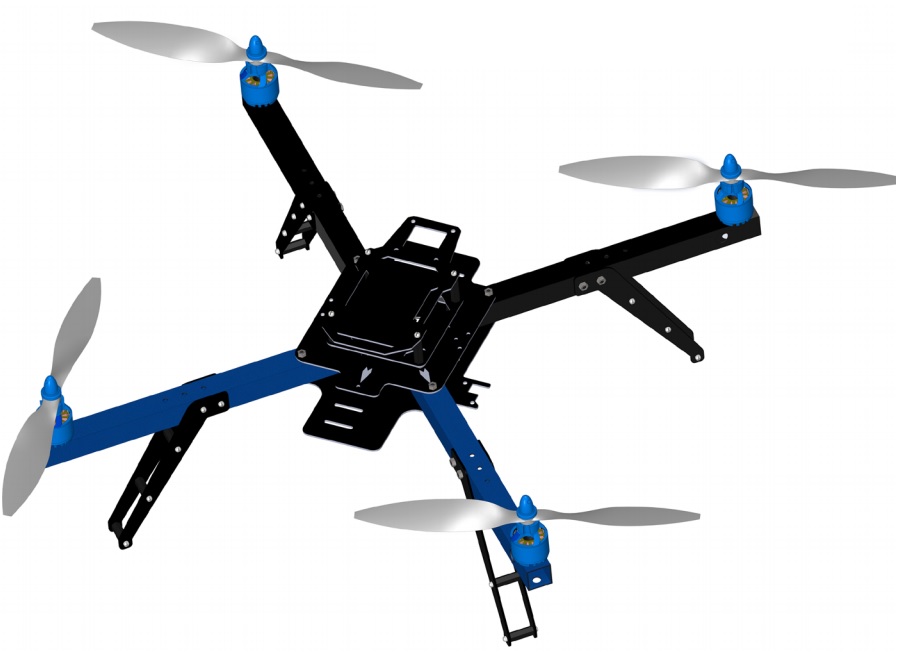
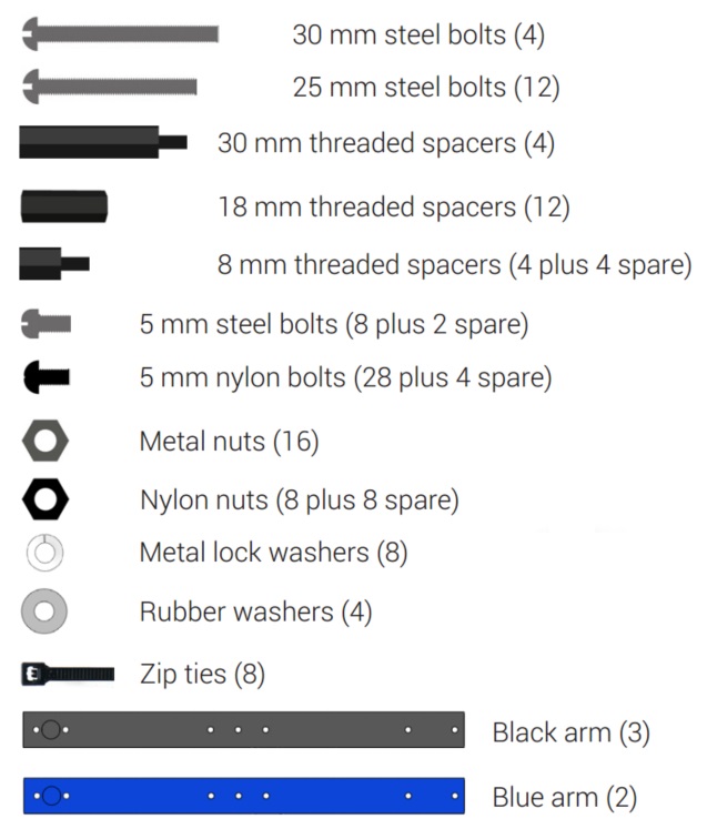
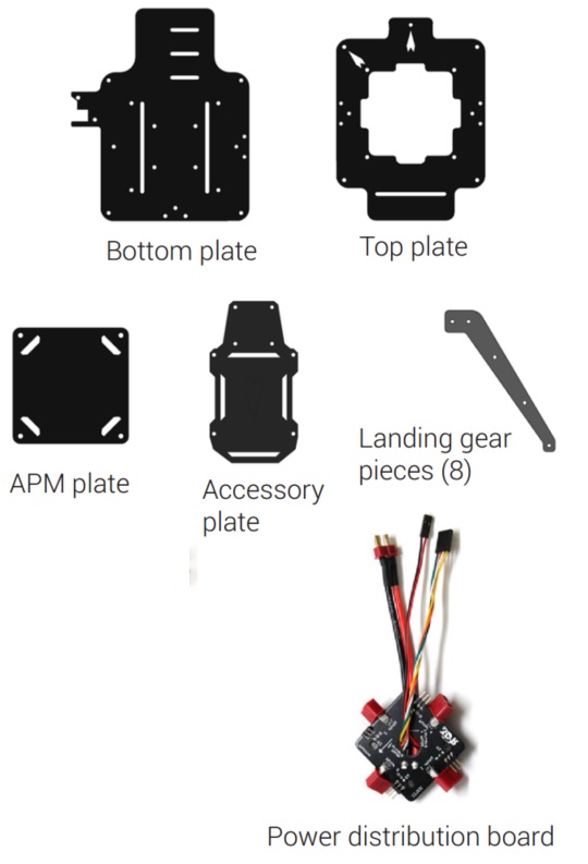
Arducopter Quad D Parts
  |   Tools Required
|
Optional Extras
Below are the suggested parts you should use with your arducopter quad, but you can also use other motors if you want.
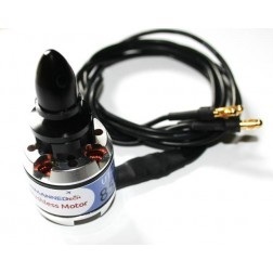 850Kv motors (4) | 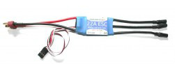 22A ESC (4) | 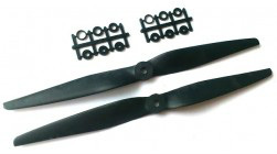 10x50 Propellers Pair (2) |
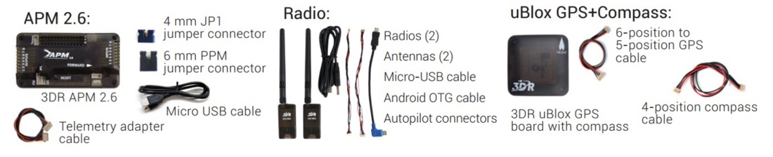
Recommended Electronics
Reccomended parts can be purchased from unmannedtechshop.co.uk
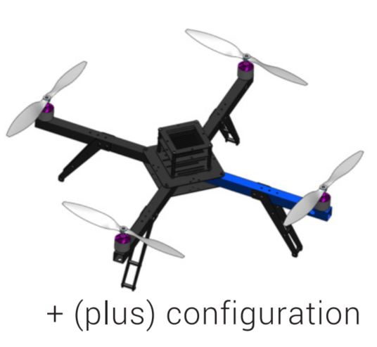
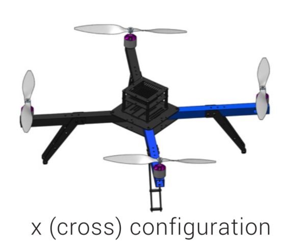
Choose + or x orientation
  |
|
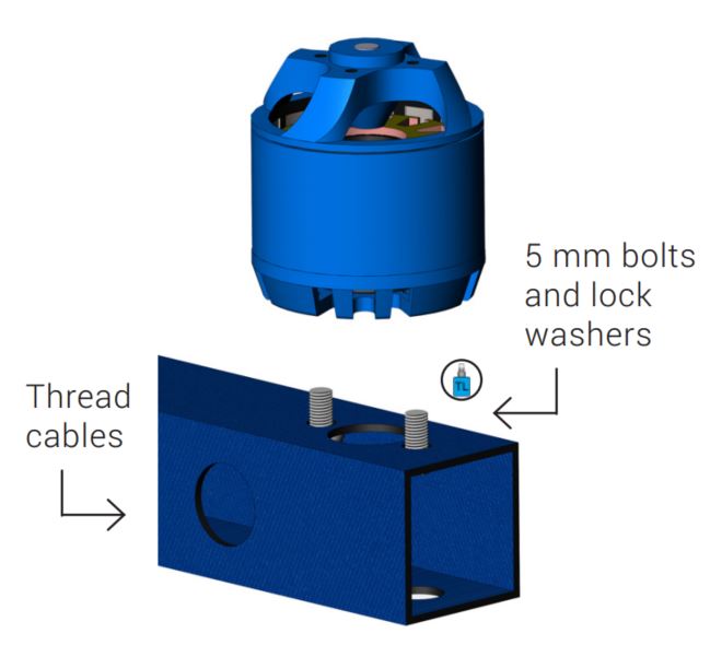
Attaching the motors to the arms
Each arm of your Quad will have a motor attached to the top of the arm using two 5 mm steel bolts and two metal lock washers. To ensure motors are securely bolted to arms, apply a small amount of threadlock to each bolt before fastening.
Threadlocking compound is an important component to ensure your motors remain firmly attached! For application tips, check out this video - http://goo.gl/ZsVyqQ
 |
|
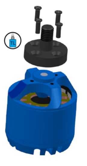 | Attach Prop Adaptors/Collets
|
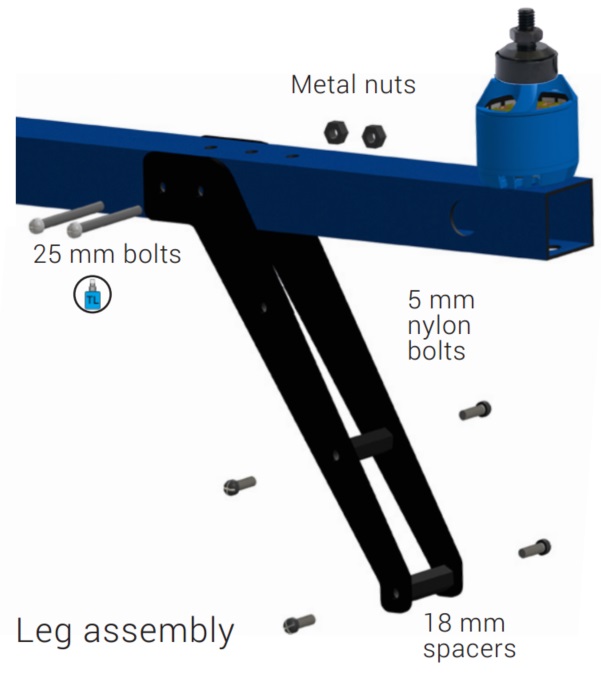
Attach the legs to the arms
 |
|
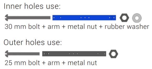
Attaching the arms to the top and bottom plates
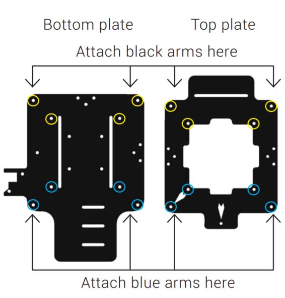  |
For plus configuration: Attach a blue arm to only the position on the plate marked with an arrow. |
 | 
|
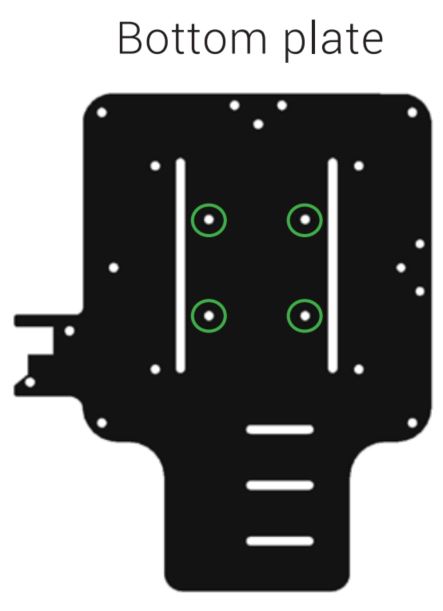
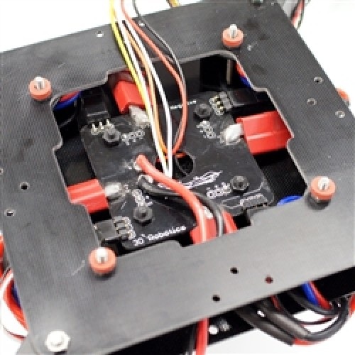
Power Distribution
 |
|
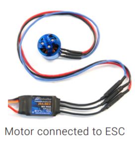
Connect Motors and ESC
 |
|
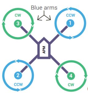 Arducopter Quad Motor Order 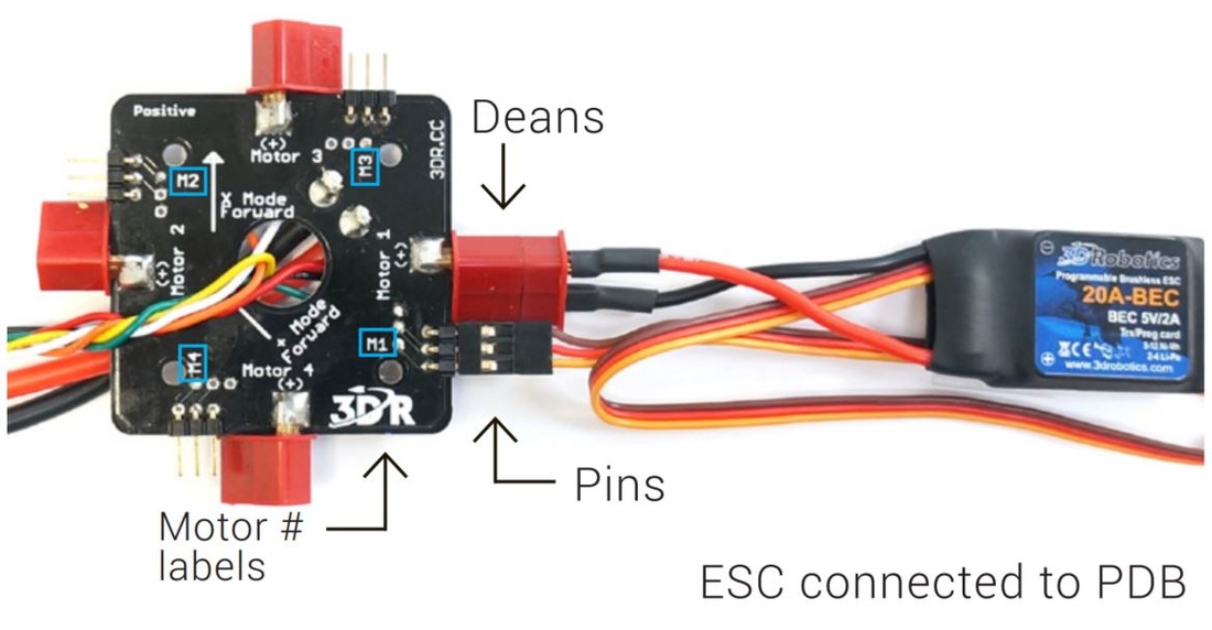 |
Don’t secure the ESCs to the frame until you have confirmed that each motor spins in the direction specified in the diagram. |
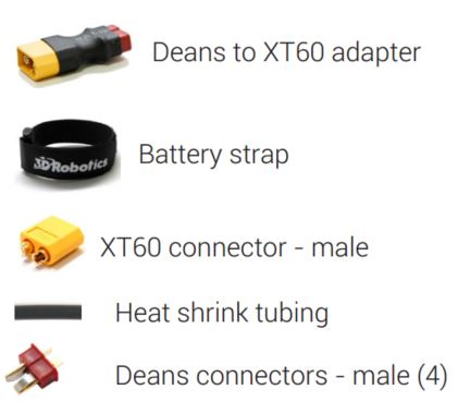
Connect power module to PDB
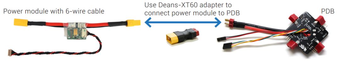
- Connect power module 6-position cable to the power module 6-position port.
- Place power module in the center of your copter near the PDB. Connect PDB red and black cable (with Deans) to power module Deans connectors.
- Use the provided Deans-to-XT60 adapter plug to connect the power module to the PDB
Install APM onto your arducopter
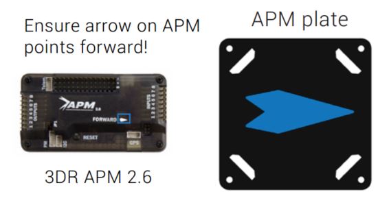 | Mount APM
Ensure mounting tape is firmly attached so the position of the APM doesn’t shift during flight. |
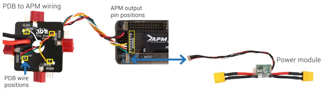 | Connect APM to power module and PDB
|
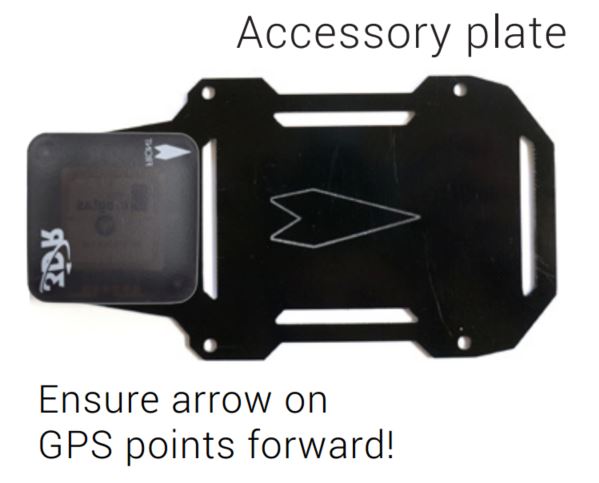 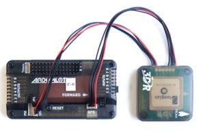 | Mount the GPS module (optional)
|
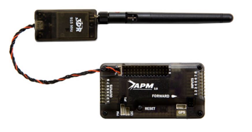 | Attach Telemetry Module (optional)
|
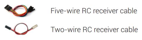
Connecting the Radio Control (RC) receiver
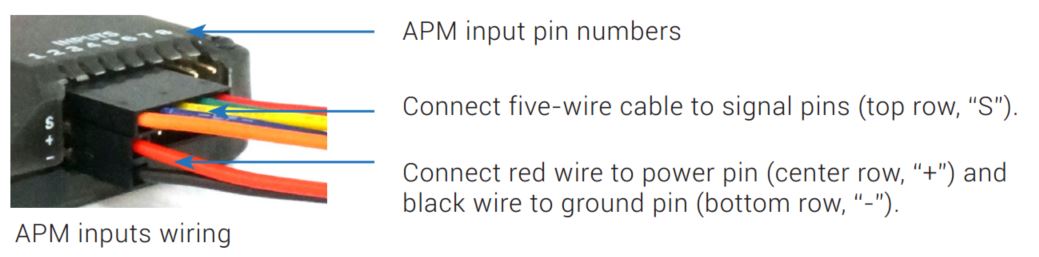 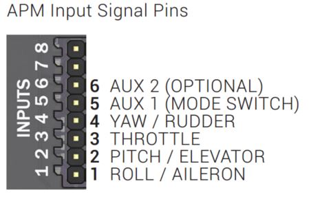 Match the correct control channel with its corresponding APM input signal pin |
Note: APM also supports one-wire PPM connection with supported receivers
|
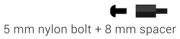
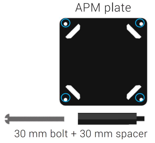
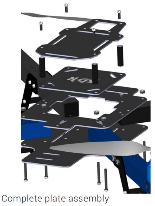
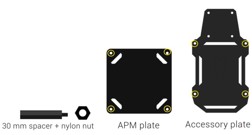
Attach APM plate to top plate
 |
|
Attach accessory plate to APM plate
  |
 |
Install/Setup the arducopter software
To configure the software and hardware on your arducopter Y6 please visit the page below for more instructions
 RSS Feed