
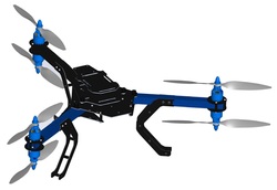
Multicopters are easy to fly, can takeoff and land anywhere, and provide great platforms for using camera stabilization systems. With three arms and six motors, the Y6 configuration combines lightweight design, powerful lifting capacity, and in-flight redundancy for a versatile copter experience perfect for any application
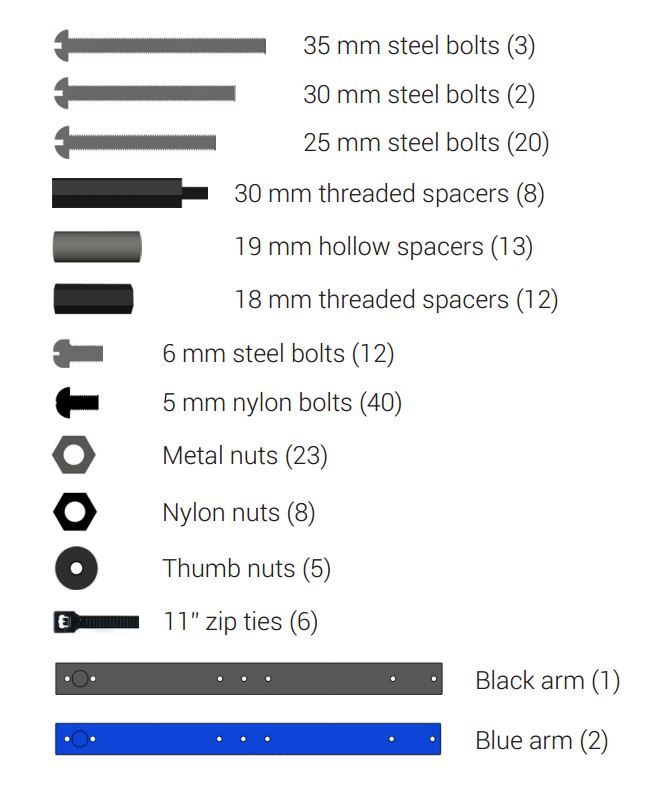
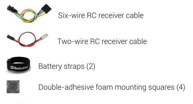
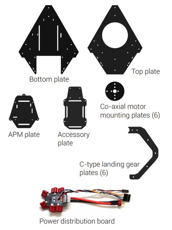
Arducopter Y6 Frame Contents
These parts are included with the arducopter Y6 frame
| 
Tools Required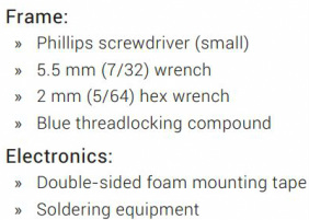
|
Optional Extras
These parts can be purchased as part of the arducopter Y6 Kit
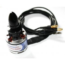
850Kv motors (6)
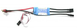
22A SimonK ESC (6)
| 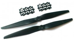
10x50 Carbon Reinforced Props (2 sets)
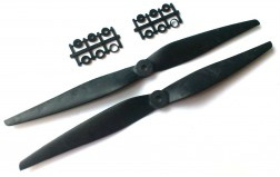
11x50 Carbon Reinforced Props (2 sets)
|
Other Electronics (depends what options you selected)
These are the required electronics for the arducopter y6, but if using other electronics, please see the instructions that came with the for installation details
| 
| 
|
Attach motors to arms of your arducopter y6 frame
Each arm of your Y6 will have a top motor and a bottom motor attached to the arm using co-axial motor mounting plates. To ensure motors are securely bolted to arms, apply a small amount of threadlock to each bolt before fastening.
Threadlocking compound is an important component to ensure your motors remain firmly attached! For application tips, check out this video - http://goo.gl/ZsVyqQ
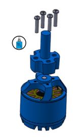
Bottom motor assembly
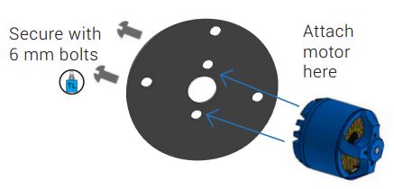
| Attach mounting plates to bottom motors
|
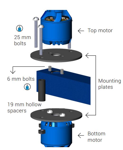
Top and bottom motors attached to arm with mounting plates
| Attach top motors to arms
|
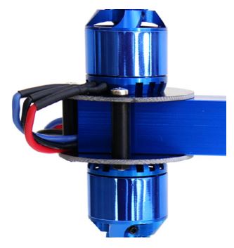
Completed Arducopter Y6 motor assembly
| Thread motor cables through arms
|
| Attach Prop Holders
|
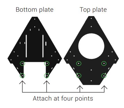
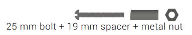
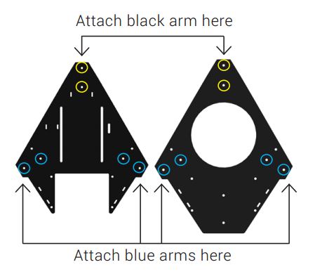
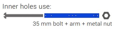
Main Y6 Frame Assembly
The top and bottom plates will form the main frame of your copter. We’ll attach these plates both to each other and to your copter’s arms.
|
|
|
|
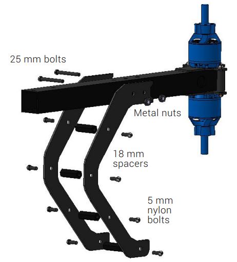
Arducopter Y6 Legs Assembly
Your Y6 has three legs, each comprised of two C-type landing gear pieces. To assemble each leg, align the two pieces and attach through four bottom holes using four 18 mm threaded spacers and eight 5 mm nylon bolts
Arducopter Y6 Leg Assembly
|
|
Power Distribution Board
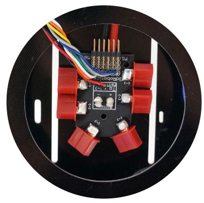
PDB between top and bottom plates
|
|
Connect motors and ESCs
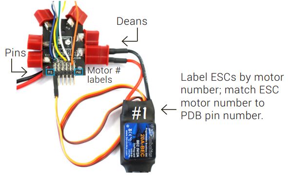
ESC connected to PDB
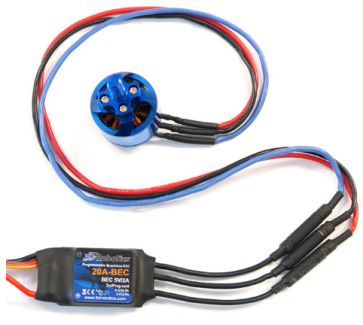
Motor connected to ESC
|
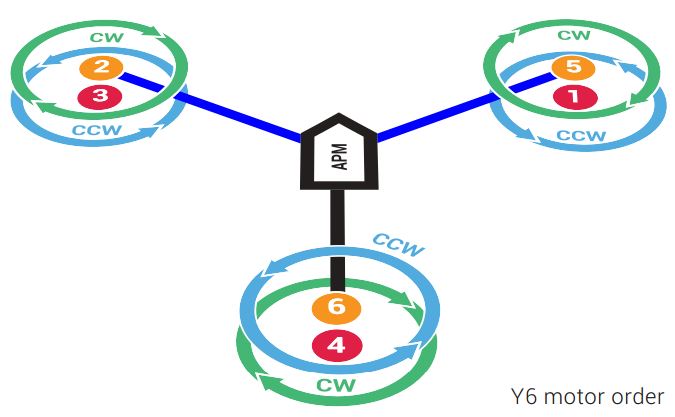
Don’t secure the ESCs to the frame until you have confirmed that each motor spins in the direction specified in the Y6 motor order diagram
|
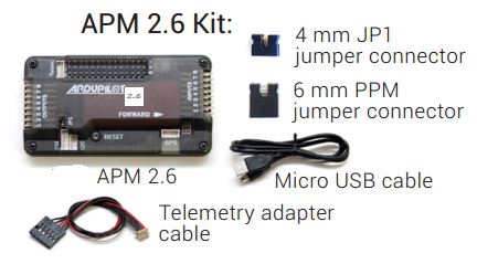
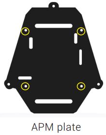
Install ArduPilot Mega onto your Arducopter Y6 Frame
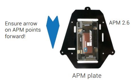
| Mount ArduPilot Mega board
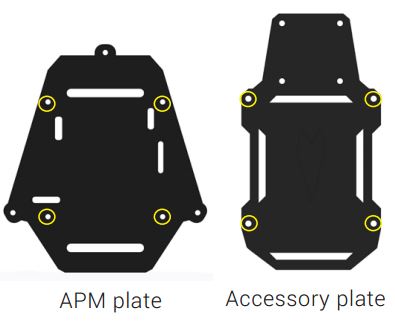
For APM 2.5: Mount APM to the top of the accessory plate |
|

|
|
|
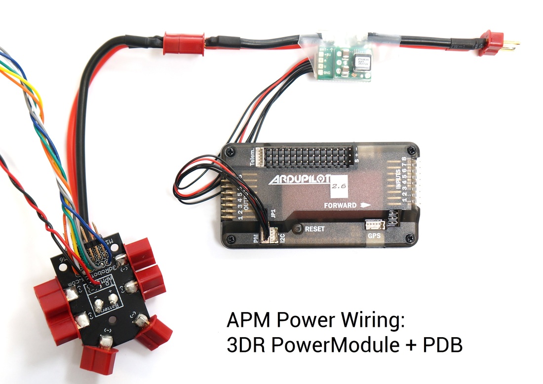
Power module connected to APM and the arducopter PDB

Connecting the PDB to APM
| Connect APM to power module and PDB
|
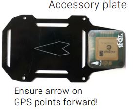
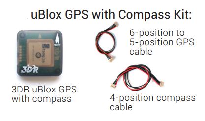
| Mount GPS Module
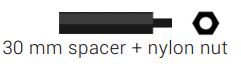
For GPS without compass: Attach GPS board to four holes using four 5 mm nylon bolts, four 30 mm spacers, and four nylon nuts. |
|
|
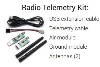
Adding Extra components to APM
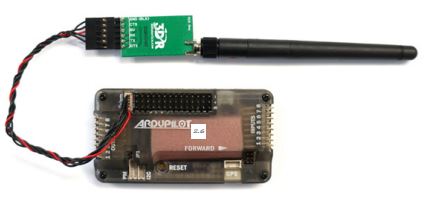
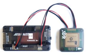
| Attaching a telemetry module
|
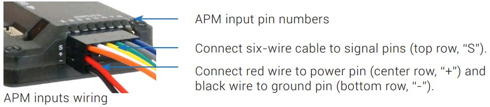
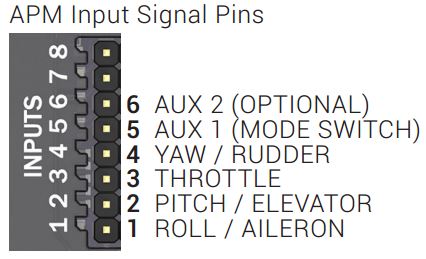
Match the correct control channel with its corresponding APM input signal pin
|
Note: APM also supports one-wire PPM connection with supported receivers. . |
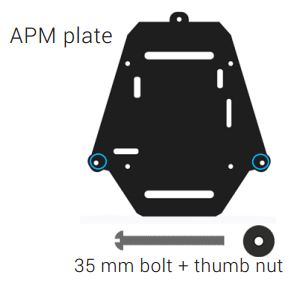
Attach accessory plate to APM plate
The last step it to attach the accessory plate to your arducopter Y6 frame, this plate can be used to mount extra gear like FPV gear/ radio modules..
|
If you have any questions visit our community forums to ask your question! Or share some flight videos/pictures! 
|
Install/Setup the arducopter software
To configure the software and hardware on your arducopter Y6 please visit the page below for more instructions
 RSS Feed