
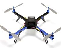
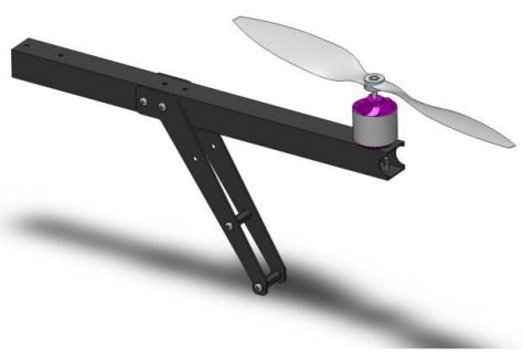
This guide will walk you through the construction for your Arducopter 3DR frame and Power Distribution board.
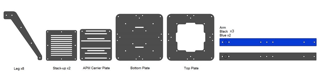
Main frame parts included with your Arducopter Quadcopter Frame
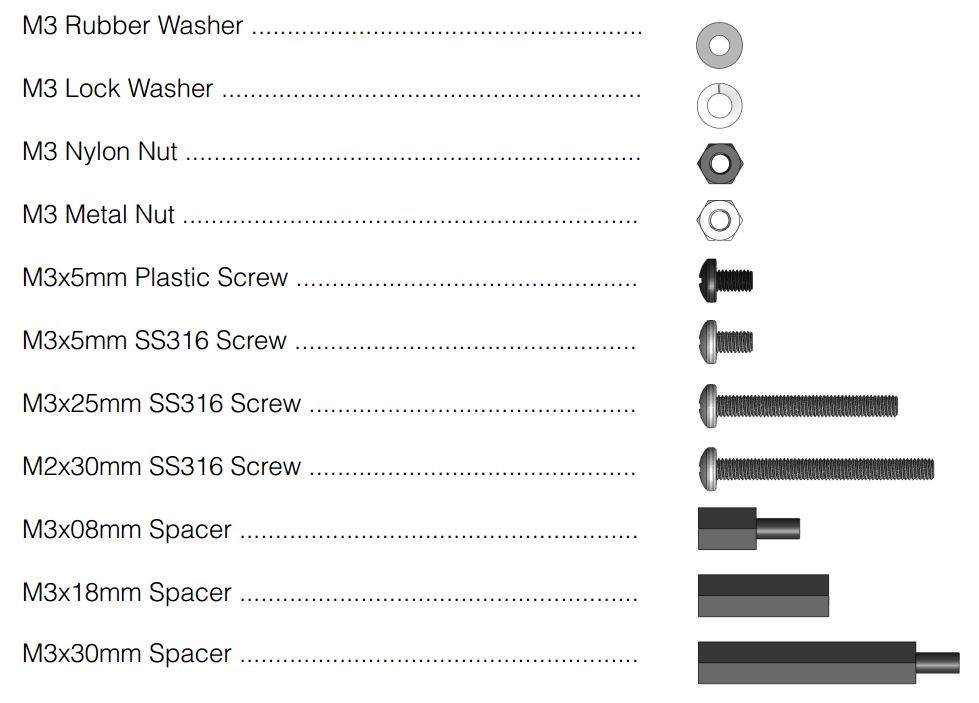
Screws and other hardware included with the quadcopter frame. Take note of the colours of the screws as they help when looking at the assembly pictures below.
Step1: Arducopter 3DR Power Distribution Board Assembly
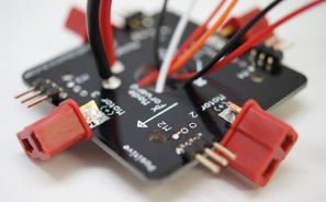
The first step it to solder/ assemble the Power Distribution Board (PDB) sot hat you can power all four of your ESC from a single battery.
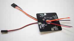
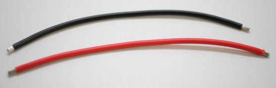
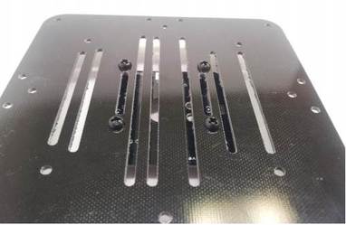
To begin, take out the PDB board and run the two sets of narrow gauge wire through the central hole.
The stripped ends of the wires should all emerge on the bottom side of the PDB, the side that says “This Side Down”.
To begin, take out the PDB board and run the two sets of narrow gauge wire through the central hole.
The stripped ends of the wires should all emerge on the bottom side of the PDB, the side that says “This Side Down”.
| Attach the narrow gauge wire as shown. Two Wire Connector
Four-Wire Connector
|  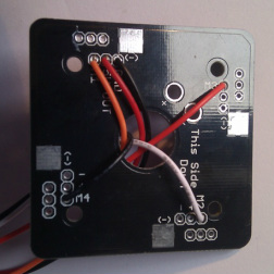 |
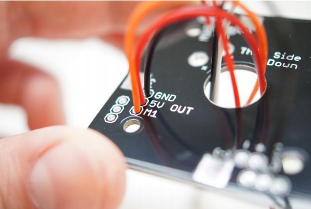

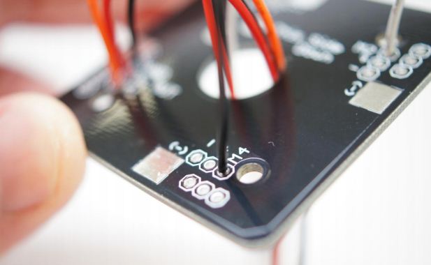
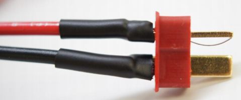
| | Now you need to attach the battery connector. Take the larger battery wires and strip the insulation off each end by about 4mm Solder the black wire into the large hole marked “-“ and the red wire into the large hole marked “+”. The markings are on the bottom of the board where you will do the soldering but the wires should emerge from the top of the board as in the image below. Be sure to include the heatshrink and then attach the male deans connector. |
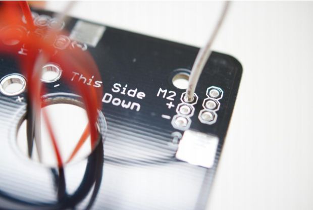
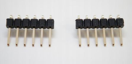
| Now you need to attach the right angle headers onto the PDB, this allows you to plug your ESC signal lines into the PDB to be routed to your ardupilot mega/arducopter. Break/snap the headers into sets of 3 pins each. Now solder the 4 sets of headers onto the PDB as shown. | |
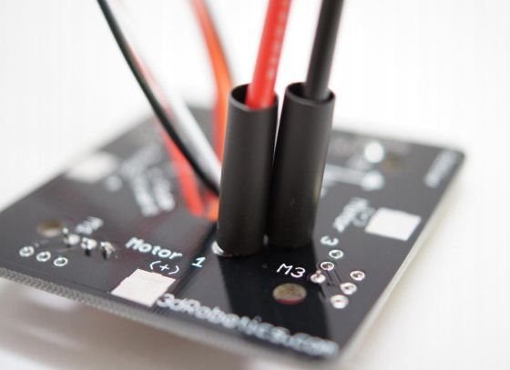
Now you need to solder a Female Dean’s Receptacle onto the exposed pads on each edge of the PDB. The connectors straddle the PCB board with one connection on one side and the other connection on the opposite side. The positive and negative sides are marked near each pad, be sure to match the markings on the PDB with the markings on each Dean’s Receptacle.
Alternatively you could also just solder the ESC wires directly to each of the Pads
Alternatively you could also just solder the ESC wires directly to each of the Pads
The final step before mounting the PDB onto the fibreglass plate is to put the velcro strap through the slits, then mount the PDB on the bottom main plate. The PDB is mounted to the frame using 4 of the M3x5mm black plastic crews, with the black plastic M3x8mm spacers, and the 4x M3 black plastic nuts. It is reccomended that you use CA glue to secure the threads.
Step2: Soldering ESC/Motor connections - if you purchased the kit
Note: If you purchased your motors (2212Q) and ESC (UT-22A-Q) from Unmanned Tech Shop, these come pre soldered with the connectors already, so you can skip this step.
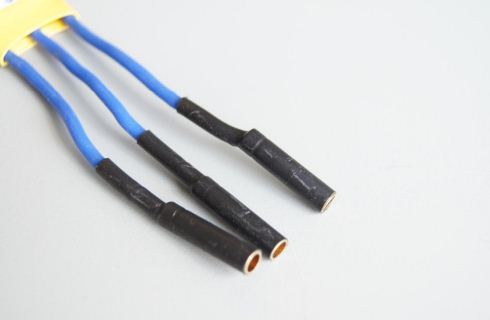
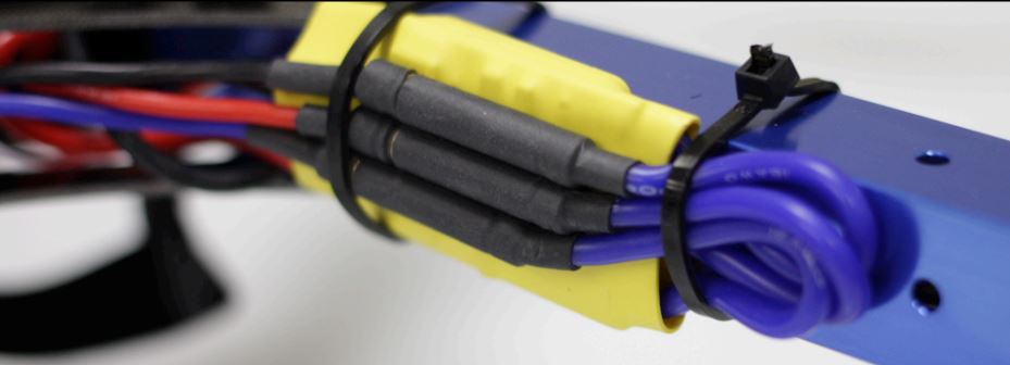
| | If you purchased the arducopter 3DR Kit that included the motors and ESC, the connectors need to be soldered too. First solder the male bullet plugs to the three motor wires. Add heat shrink to cover the connector from the solder joint up to the lip where it meets the female side when connected |
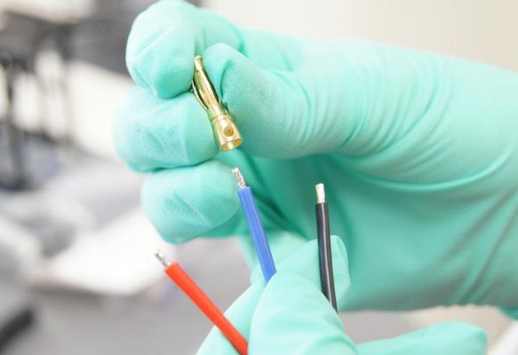

| Repeat the same setps for the ESC connections with the female bullet connectors. Cover with heatshrink covering all of the exposed metal tip. | |

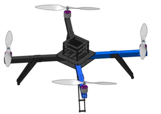
Step3: Arducopter 3DR Frame Assembly
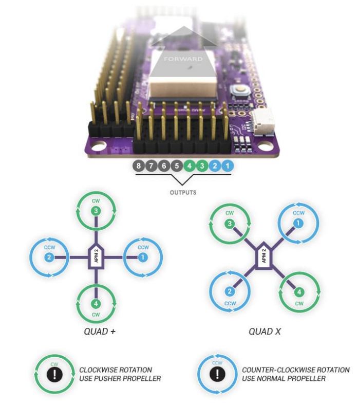
Choose Frame Orientation X or +
 Arducopter X Configuration | 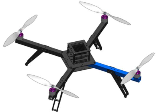 Arducopter + Configuration |
Something to keep in mind during this build is which configuration your vehicle will be flown in. This is later chosen when setting up your APM in the Mission Planner. There is no effect on performance it is just a matter of personal preference. Both the + (Top)
and X (Bottom) configurations are pictured above. The blue arms indicate the front of the vehicle. This manual will continue building the vehicle in X configuration. Please adjust accordingly.
and X (Bottom) configurations are pictured above. The blue arms indicate the front of the vehicle. This manual will continue building the vehicle in X configuration. Please adjust accordingly.
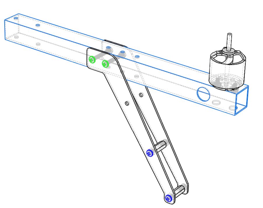
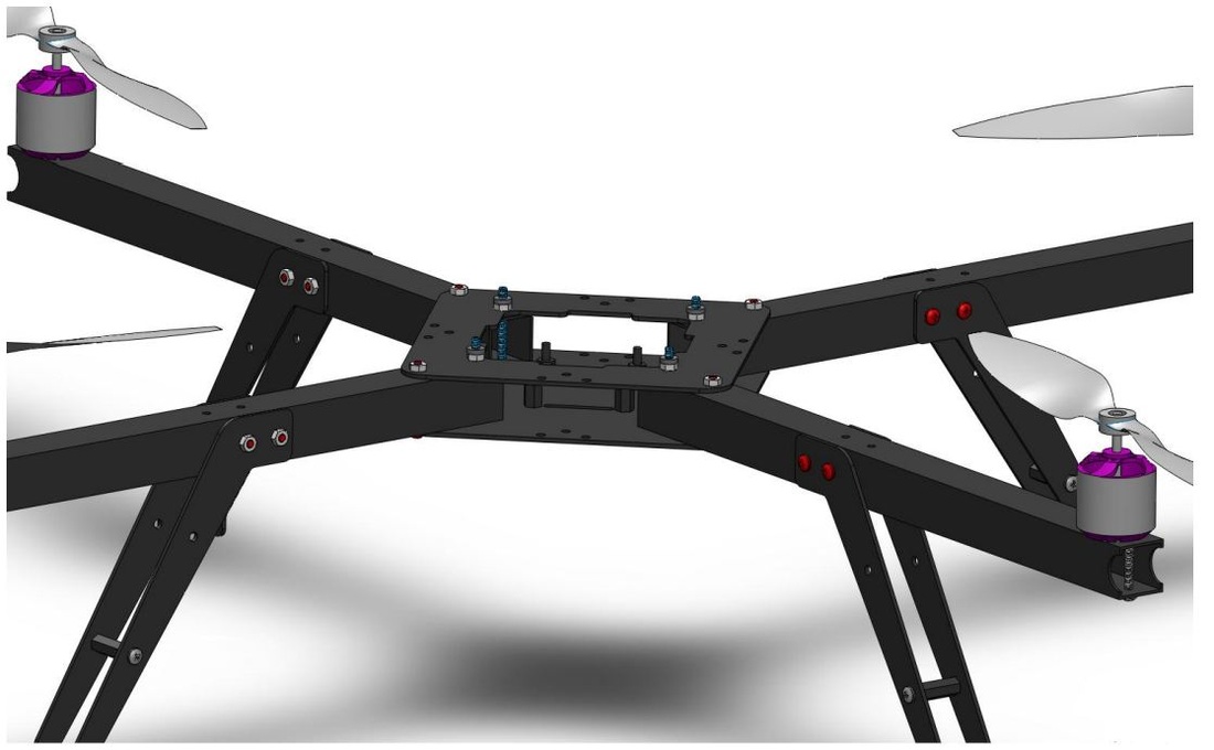
3a: Arm Assembly
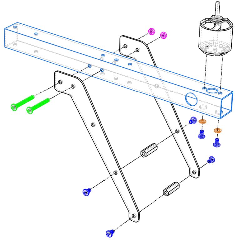
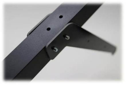
- Attach the motor to the arm using two M3x5mm screws (Blue) and two M3 lock washers (Orange) making sure the screws go into the threaded holes in the motor and not the ventilation holes. (If the motor is screwed using the ventilation holes, it will not spin freely) Route the motor cables through the hole on the side of the arm
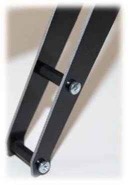
- Use two M3x25mm screws (Green) and two M3 metal nuts (Pink) to fasten the legs to the arm using the indicated holes. To provide rigidity to the legs attach two M3x18mm spacers in between the legs and secure with four M3x5mm metal screws (Blue)
- Repead for all 4 arms
 |   |
3b: Main Plate Assembly
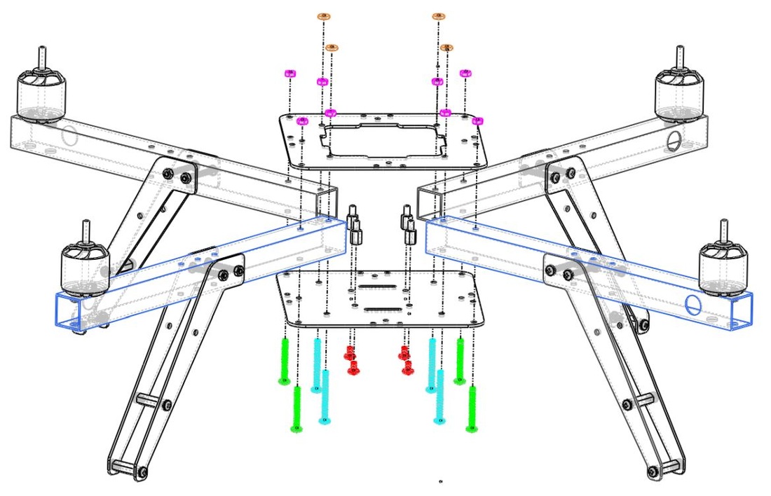
- Attach the bottom and top plates to one of the arm assemblies using an M3x30mm screw (Blue) and an M3x25mm screw (Green), secure with two M3 metal nuts (Pink),. Note the four screws closer to the center of the vehicle are longer than those on the outside. This 4 longer screws will be used to hold the PDB cap and stack-up assembly.
- Repeat for the other three arms
- Attach four M3x08mm spacers as indicated in the figure above and fasten using four M3x5mm nylon screws (Red).
- Slide the velcro straps through the two slots on the bottom plate. The velcro straps will be used to fasten the flight battery bellow the vehicle
- Slide four rubber washers (Orange) onto the M3x30mm screws (Blue) that stick out of the top plate
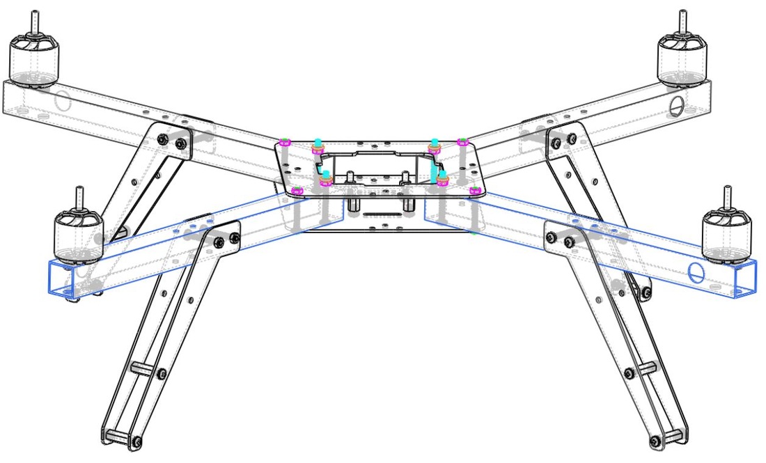
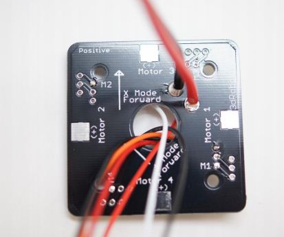
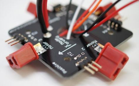
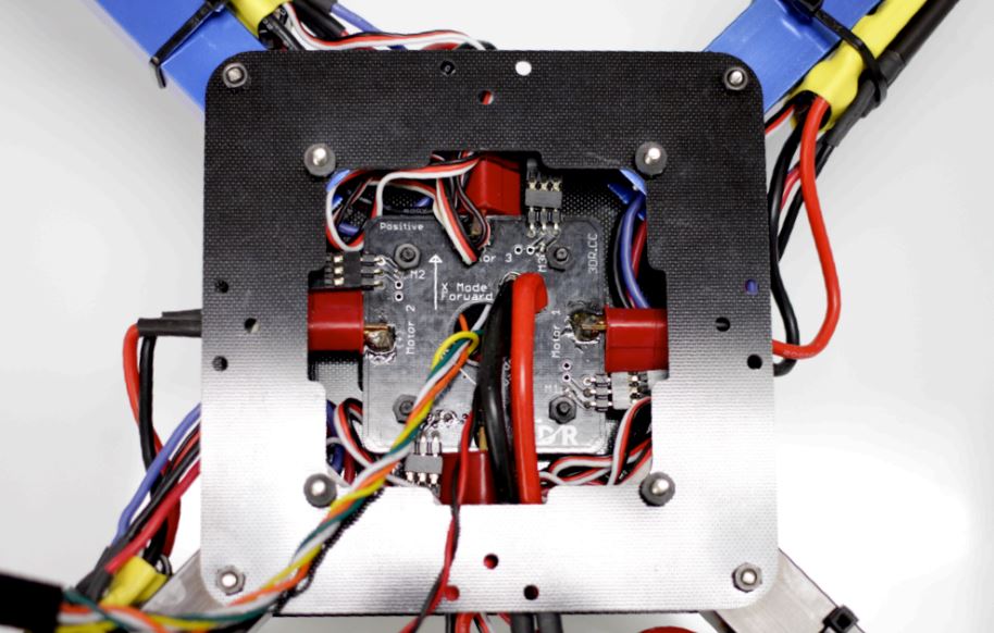
| If you want you can also insert the Power Distribution Board onto the nylon spacers on the center of the frame. Remember to set the orientation correctly and the right way up (the bottom of the PDB board will have a label saying This Side Down). You can also connect your motors and ESCs together via the bullet connectors. You can mount your ESC to the arms using the included zip ties. | 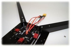 |
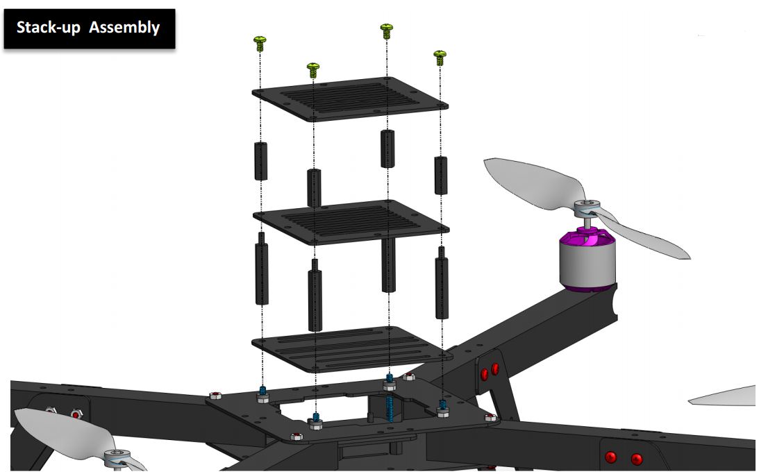
3c: Stack-up Assembly
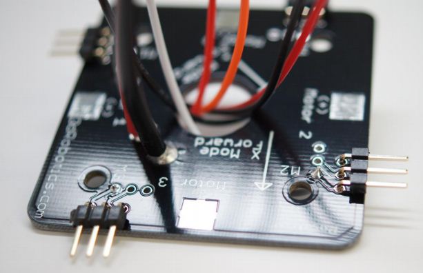
| Next install the Base Cap, note that the two slots close together (marked in Blue) mark the front side of the quad. Align them with the front arrow on your pdb. For setting correct motor orientation plase visit the arducopter wiki (http://code.google.com/p/arducopter). The Base Cap allows for easy access to the PDB as well as the motor wires. Screw 4x M3x30mm Spacers to hold the Base Cap in place. The stack-ups fit right on top secured on top by 4x M3x05mm Nylon screws (Green) Your ArduPilot Mega flight controller is simply mounted onto the base cap, you can use some nylon screws or some double sided tape. Double sided tape is better since it reduces some of the vibrations You can mount extra add-ons like a Telemetry Kit or a GPS upgrade onto the stackup plates | 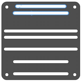 |
Step 4: Setting correct motor orientation
An image is provided for referance, but for more information about connecting your ardupilot mega electronics, please look at the arducopter quickstart guide.APM can be mounted using double sided tape (3M Scotch Exterior Mounting Tape is recommended) or it can be bolted to the carrier plate. The series of slots on the carrier plate allow your APM to be bolted in both + and X configurations.
Note: In + mode the front of the APM should face arm 3. In X mode the front should be between arms 3 and 1.
Note: In + mode the front of the APM should face arm 3. In X mode the front should be between arms 3 and 1.
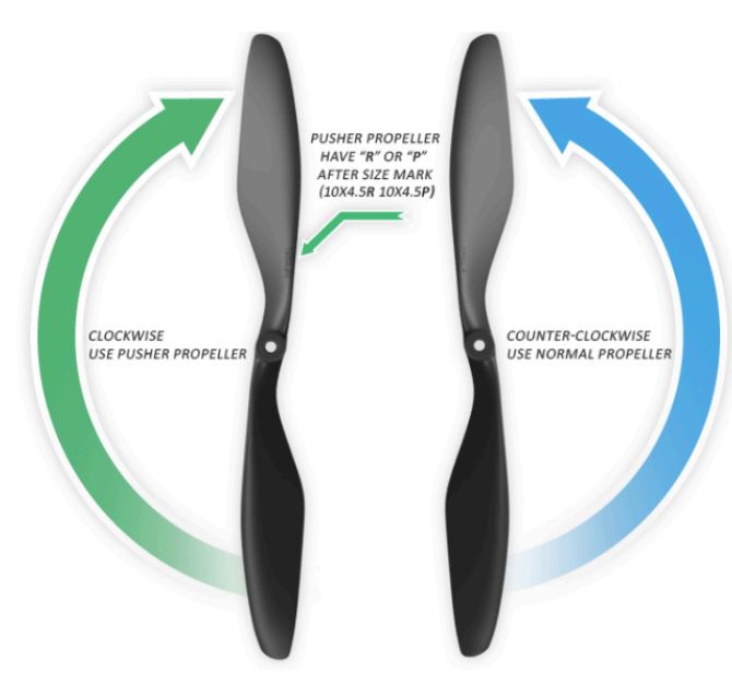
To attach the propellers use the collets included. Cut the plastic ring included with the propellers that fits snug around the threaded collet and insert it into the slot in the back of the propeller. Place the collet on the motor shaft and tighten to keep the propeller in place. Make sure the writing on the propeller is facing up. Refer to the diagram above for correct prop rotation direction. Note: It is recommended that you balance your propellers prior to installing.
For more details on connecting your ArduPilot Mega board to your frame and setting everything up have a look at our arudcopter quickstart guide
We hope you enjoy your Arducopter 3DR-C. If you have any questions or concerns please feel free to ask a question below or on the forums!
 RSS Feed