
If you are not using the standard Arducopter Power Distribution Board this quide will show you how you can easily connect your ArduPilot Mega/ Arducopter Board with the rest of your frame. Read more for more details
The standard Arducopter Power Distribution board has special connectors to plug directly into the ArduPilot Mega autopilot. However if you are not using this board because you are using a different multi rotor frame, this guide will quickly show you how you can still connect everything together.
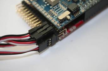
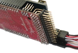
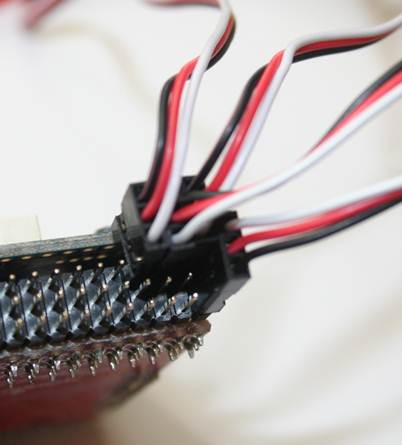
If you do not want to use any special cables or connectors you can simply plug the ESC connections into your ArduPilot Mega board. You must not connect all of the ESC plugs normaly, as this will cause some interference with the electronics, so only connect one ESC plug normally, and then simply connect the remaining upside down as shown. This means that only the signal line between APM and your ESC are connected for the remaining ESC's. Make sure that the connections are not going to come off easily. If they are loos you should use some sticky tape to hold them in place, as you dont want one onf them coming loose during your flight.
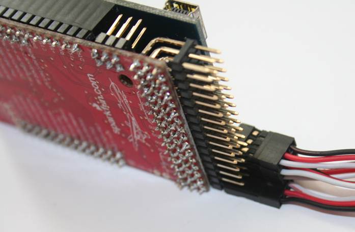
Click image for full size
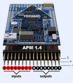
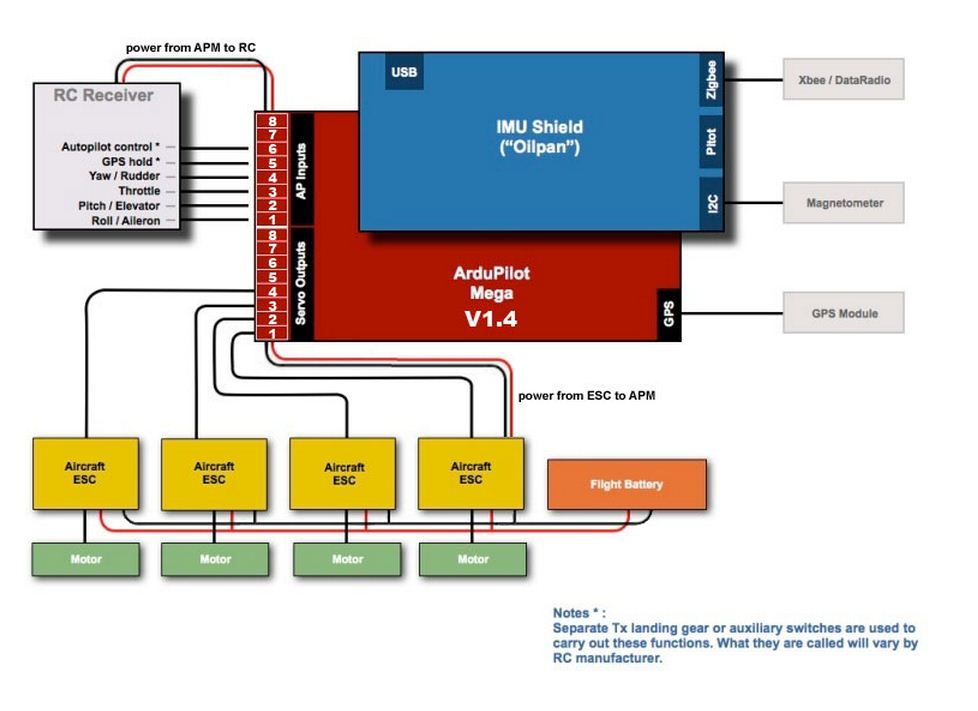
The most simple method is to simply connect one of your Electronic Speed Controller cables into the ArduPilot Output pins. Depending on your configuration, you need to match each motor to the appropriate output so Arducopter knows where each motor is. For more information the connection please look at the Arducopter Wiki. We have included some images of the most common setups. Simply connect the relevant motor/ESC to the corresponding output pin.
 RSS Feed