
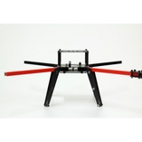
This guide will show you how to assemble your Lunar Lander 4 Quadcopter frame.
Soldering the Quad Power Distribution Board
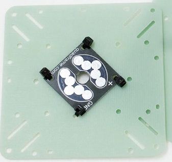
In order for you to be able to power all of your motors with a single battery, you need to solder the connections onto your power distribution board. A diagram is shown below explaining how to do this.
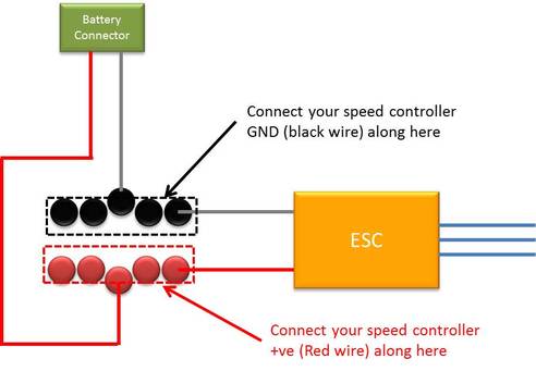
How to solder your Quad Power distribution board
Simply solder all of your Speed Controller GND connections (black wires) along the GND pads on the distribution board, similarly connect all of the +ve (red wire) of your Speed Controller onto the + pads.
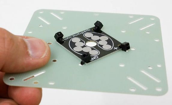
There are two extra pads on the distribution board that are used to attach your battery connectors, remember to connect the positive battery cable onto the + side of the board, and GND to the GND side of the board.
There are two extra pads on the distribution board that are used to attach your battery connectors, remember to connect the positive battery cable onto the + side of the board, and GND to the GND side of the board.
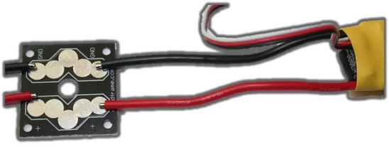
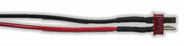
Battery connection cable with a Deans connector
You can use any battery connector you choose for the connection cable, such as the popular Deans connectors, or XT60 connectors. You will also need some extra wire depending on how long you want this connection to be.
Lunar Lander Quad copter Centerplate Assembly
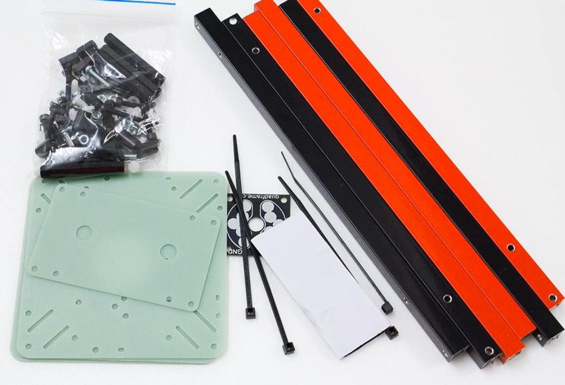
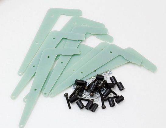
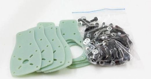
The first step is to construct the quadcopter central assembly. To do this you will use the following items:
- 2x main square plates
- 4x Aluminium arms
- power distribution board
- battery holder plate, and velcro
- zip ties
- bag of fasteners, nuts and bolts, spacers etc...
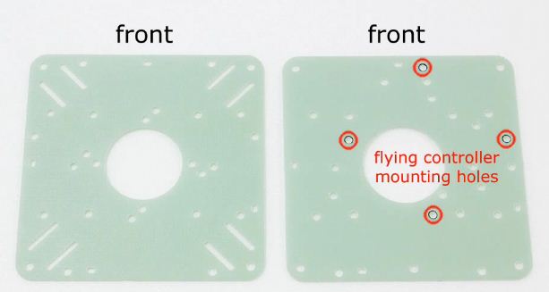
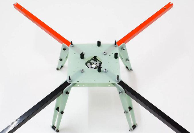
Once of the main square plates has holes to mount your flight controller, depending on the flight controller you are using, you will need to choose the relevant holes. The other main square (left of image) has holes for the quadcopter legs to fit into, do not mount your flight controller on this plate, this plate is used to mount your Power Distribution Board..
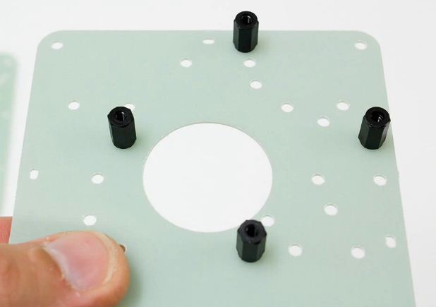
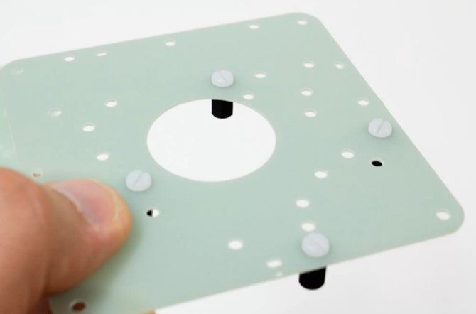
Mount the stand-offs for the flight controller using the 10mm spacers and nylon bolts as shown below
On the other main square plate, you can mount your power distribution board using the zip-ties as shown in the images below. You can cut of the ends of the zip-ties for a neat finiish.
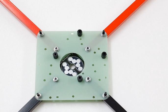
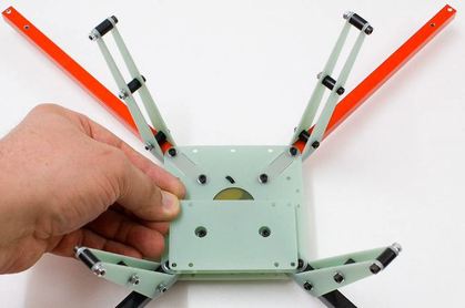
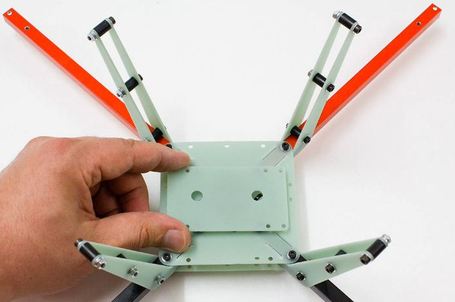
Once the flight controller sandoffs and the PCB have been attached to the main squares, the next step is to connect the arms. To do this you will use the 15mm screws on the inner section of the plate, and the longer 25mm screws on the outer holes. Make sure that the flight controller square plate is on top. It also is important to make sure you use the washers and spring washers for this step to make sure the screws/bolts do not vibrate loose when you are flying. Do not over tighten the bolts at this stage as you still need to attach the Lunar Lander 4 Quadcopter landing legs in the next step.
Quad copter Landing Leg Assembly
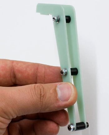
Lunar Lander 4 landing legs
You will now build the landing legs of your quad copter. To do this you will use the 18mm screws, and 10mm spacers. Take two legs, and plase the screw through on of them, then attach the spacer, and finally put the other leg on. You will need to tighten the legs with a bold and washer. It is important to leave the top screw loose so that you can easily attach it to the central assembly.
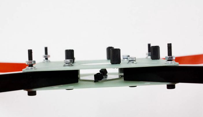
Once the legs are constructed you will mount them between the two main square plates and the arm. Once the legs are in place you must now tighten all of the screws and nuts.
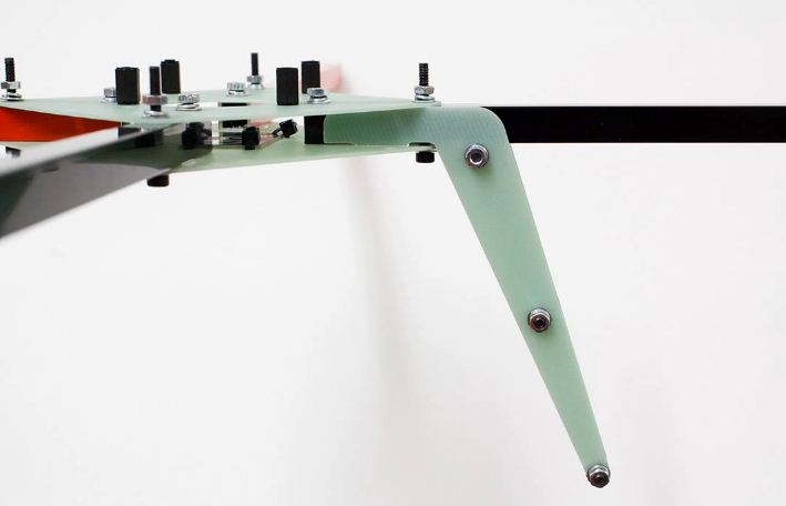
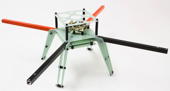
Lunar Lander 4 frame with legs attached
Attaching Quadcopter LiPo Holder
There are two methods for mounting the batter holder and are shown below. You will need to mount the battery holder plate using the remaining 16mm screws and 10mm spacers
Using GoPro camera mount
Battery holder should be mounted towards the rear if you are going to use the GoPro camera mount
No camera mount
Battery holder can go in the middle of the quad copter if you are not using any camera mount
Mounting electronics protection plate
Quad copter electronics protection plate
The electronics protection plate is mounting using the very long spacers which are attached to the outer screws that you used to assembly the central assembly. This plate will help protect your electronics if you ever flip your quad copter.
Assembling Motor Mounts (optional)
The final step is to assembly the motor mounts. You can always skip this step and mount your motors directly onto the arms.
The motor mounts extend the outer quad copter frame diameter allowing you to use larger motors/propellers
The motor mounts extend the outer quad copter frame diameter allowing you to use larger motors/propellers
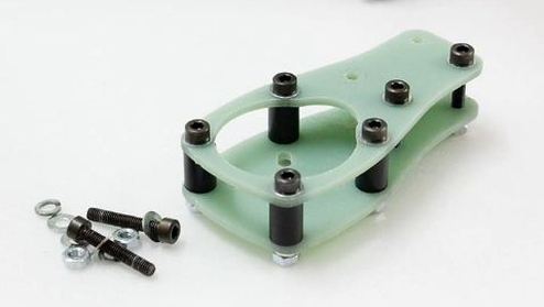
Assembled motor mounts
Using the 10mm screws and 10mm spacers build the motor mounts as shown in the image. Remember to use the washers. Do not make the bolts too tight as they will need to go over the aluminium arms in the next step
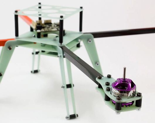
The final step is to then attach the motor mounts onto the aluminium arms, you will then need to tighten all of the bots to secure the motor mounts
There are two methods for mounting your motors as shown below. This will depend on the type of motor you are using. You can mount your motors in the most common upright position (left) but you can also mount them in the upside-down position as shown in the image to the right.
There are two methods for mounting your motors as shown below. This will depend on the type of motor you are using. You can mount your motors in the most common upright position (left) but you can also mount them in the upside-down position as shown in the image to the right.

Congratulations, the frame has now been completed. We hope you have a successful flight! If you have any questions or suggestions please post a comment below.
 RSS Feed