
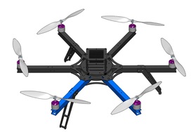
This guide will walk you through the assembly process of your Arducopter 3DR Hexa-B Frame.
The 3DR ArduCopter Hexa is a stable and supported multi-rotor frame in the ongoing development of the ArduCopter codebase on DIYDrones. It features a very durable Aluminum and G10 FR4 frame that can withstand hard impacts. The wide legged stand allows for more stable takeoffs and landings and provides an unobstructed view for a bottom mounted camera.
The main features of revision B, is that it has shorter arms which reduces the weight.
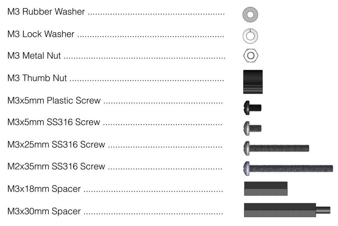
Hardware Included with the Arducopter Hexacopter.
Screws and other hardware included with the hexacopter frame. Take note of the colours of the screws as they help when looking at the assembly pictures below.
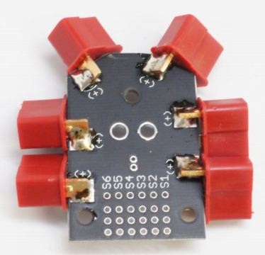
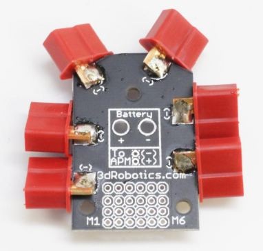
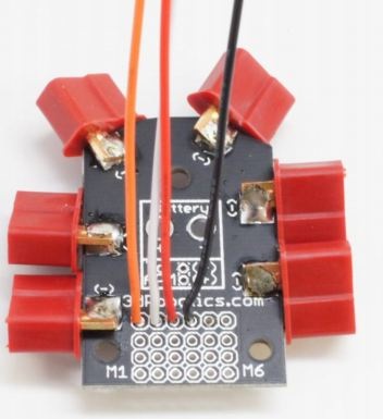
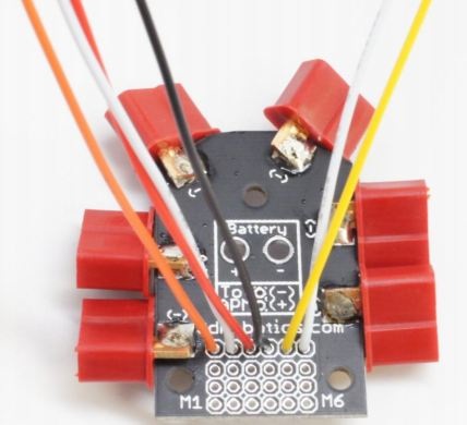
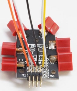
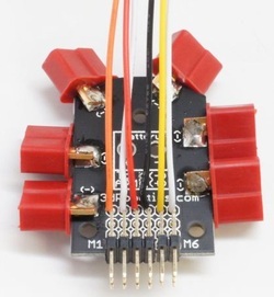
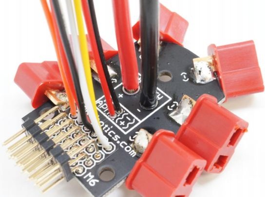
Soldering the Power Distribution Board
 |
|
  |
|
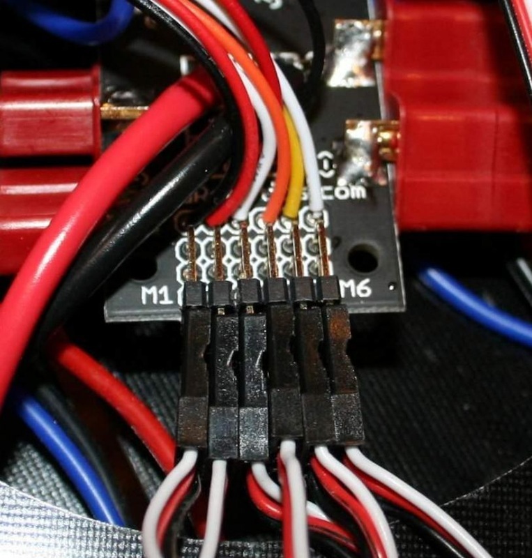
 | Please note that depending on supply the colours of the cables may vary, just make sure you keep the same order so you know what colour should go to which motor.
|
 |
|
 |
|
 |
|
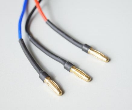
 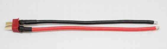 | Depending on supply a pre-soldered cable may come with your kit so you don't need to do this.
|
 |
|
 |
|
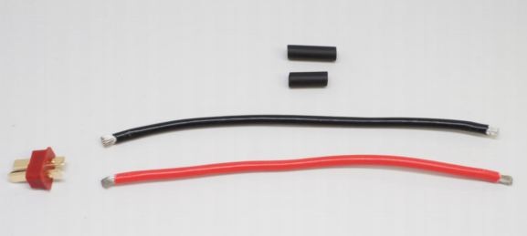
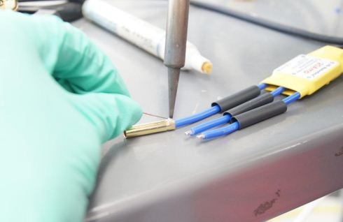
Soldering the motor/ESC connections
 | If you purchased the kit from Unmanned Tech, the motors and ESCs will come pre-soldered so you just need to connect them. If that is is the case you can skip this section
|
 |
|
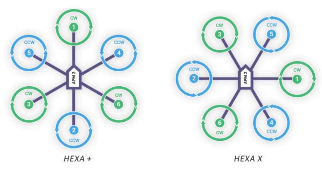
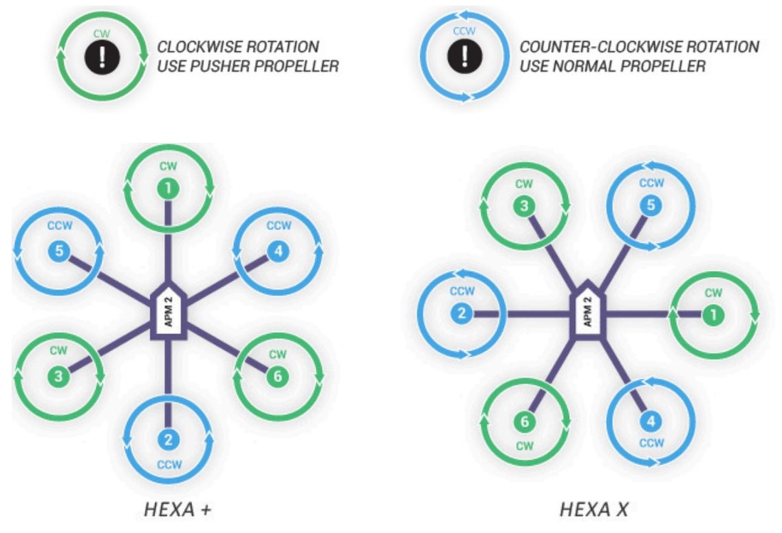
Choosing your Hexacopter frame orientation
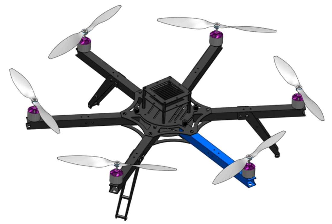 Arducopter Hexa + 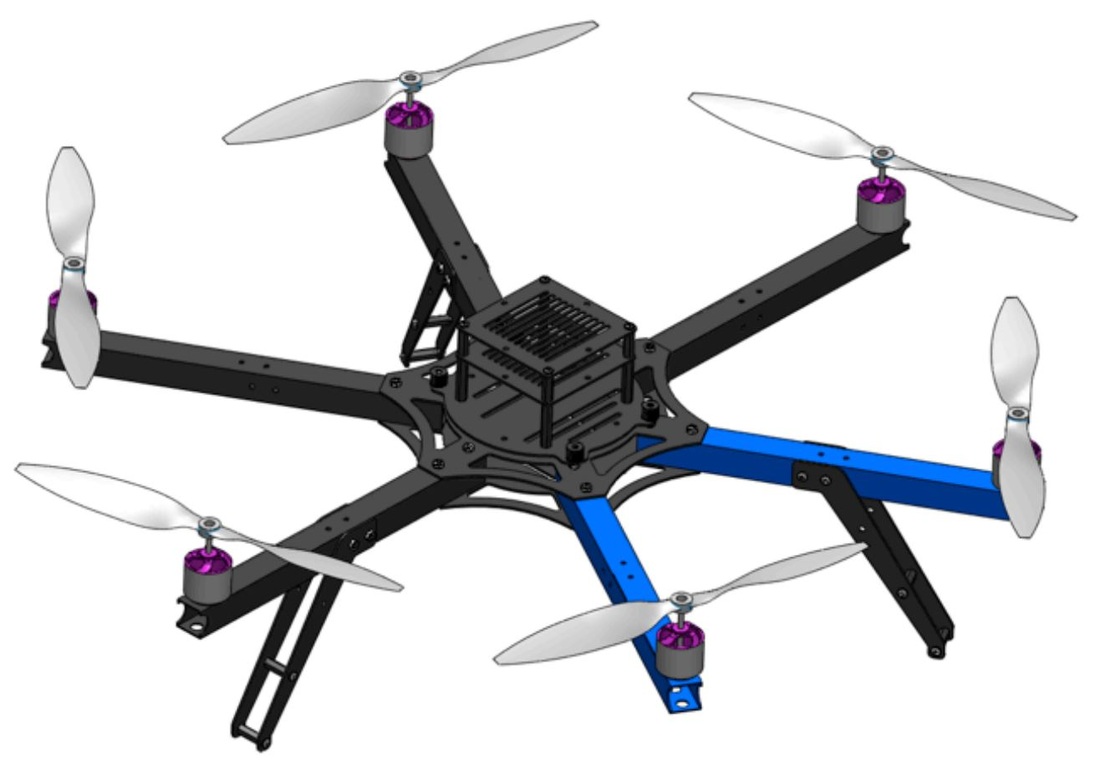 Arducopter Hexa X |
Notice which color arms have legs mounted on them for each configuration |
Assembling your arducopter arms - x6
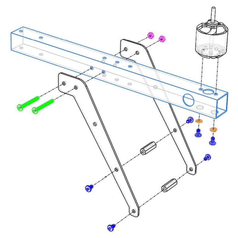 Arducopter Leg Assembly - click for larger view 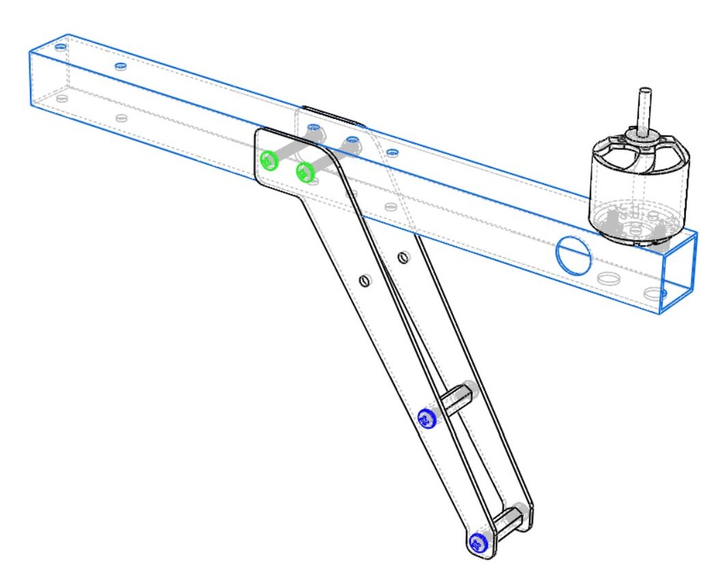 | Please note that only 3 legs will have legs on them. Refer to the pictures above to select which color arms will have legs on them
|
Building the central part of the arducopter Hexa frame
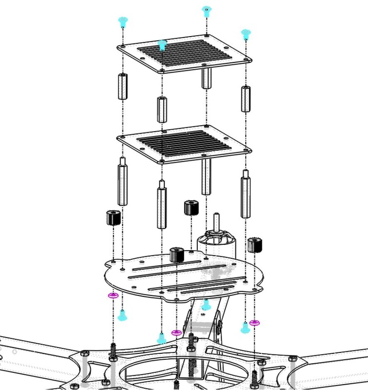
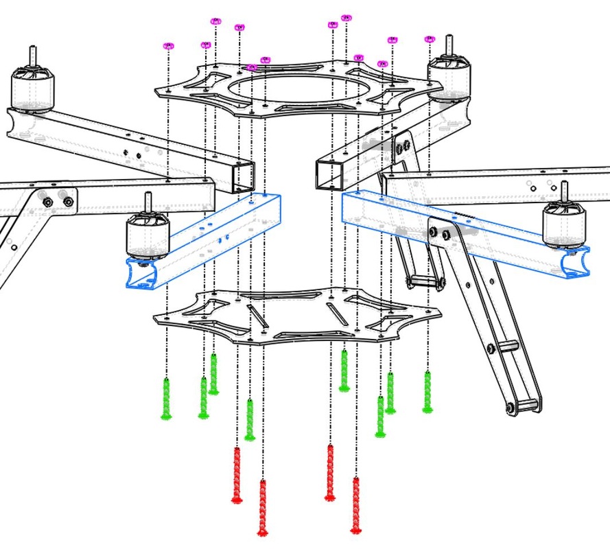 Arducopter Hexa Frame Assembly - click for larger view 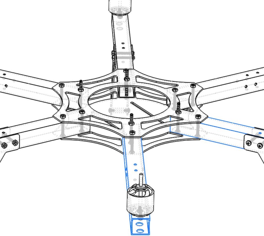 |
The screw closer to the center of the vehicle is longer. You will end up with four longer screws that will be used to attach the PDB cap
|
Wiring everything together
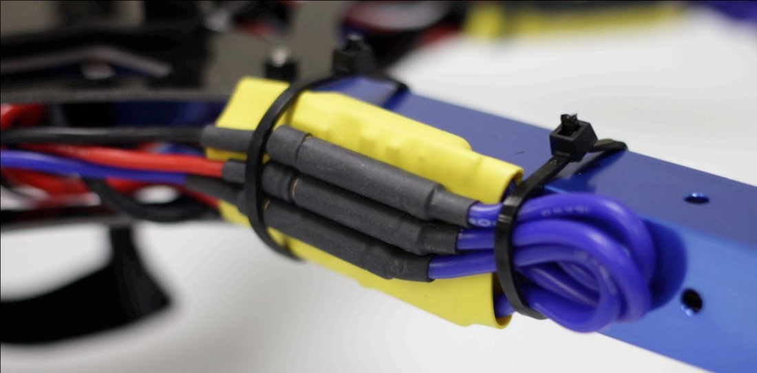 |
Its a good idea to wait before you secure the ESC too tightly with a zip tie. When configuring arducopter you will need to make sure the motors are spinning in the correct direction. To change the direction you swap the two outer wires of the ESC around. If it has already been secured this might be difficult. |
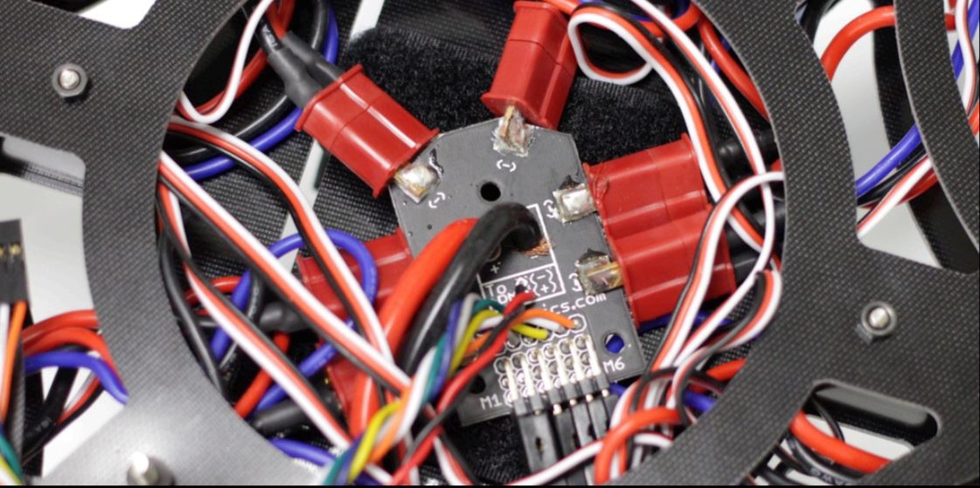 |
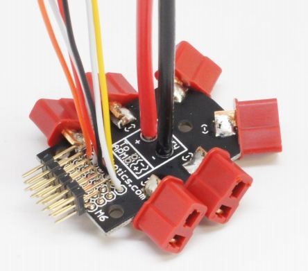
Although orientation does not matter, some orientations might allow you to route wires more neatly. It is recommended that the PDB pins face the same direction as your APM output pins to minimize the distance between them
The order does not matter, this is just so the motors can get power from the battery |
 |
|
 |
The ESCs are currently left dangling and unattached to the frame. This is because later on we will start up the vehicle and verify the motors rotate in the correct direction. To reverse motor spin direction, swap any two of the three wires connecting the motor to the ESC. Once all the motors spin in the correct direction use the zip ties included to mount the ESCs to the vehicle’s arms |
Mounting your ArduPilot Mega board to the Hexacopter
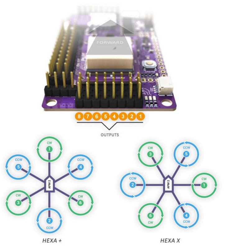 |
In + mode the front of the APM should face arm 1. In X mode the front should be between arms 3 and 5
|
Assembling the arducopter hexa Stackup plates
 Arducopter Stackup Assembly - click for larger view 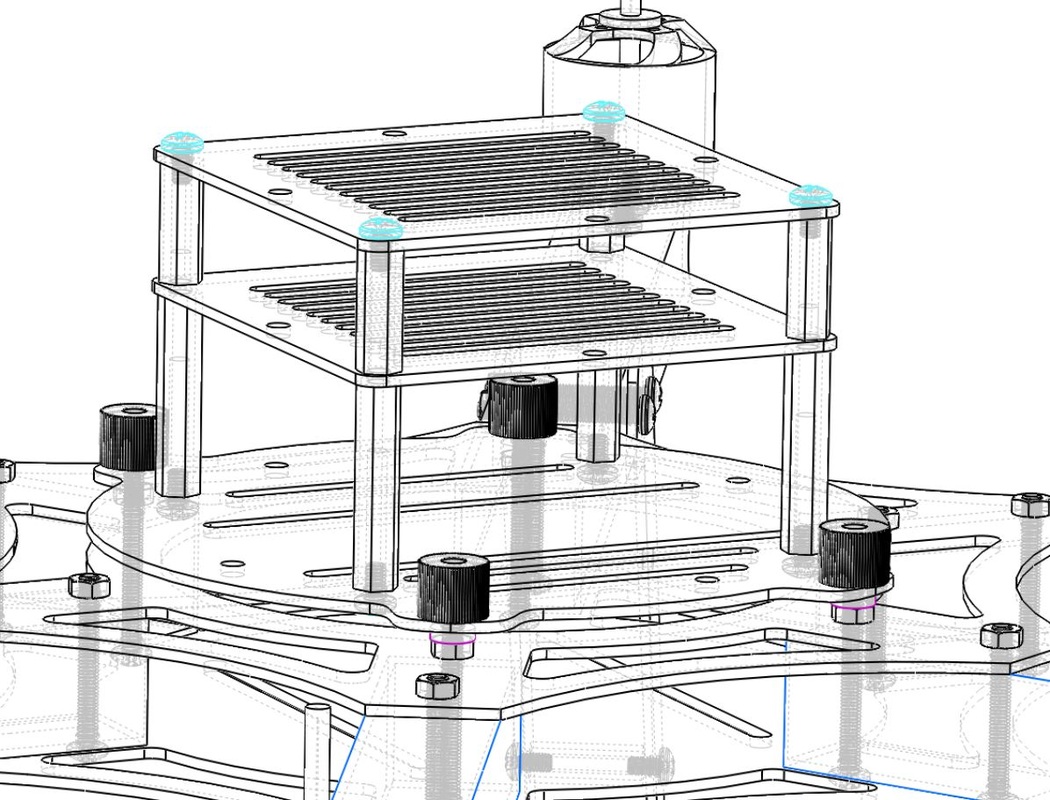 |
The diagram illustrates the X configuration. For + you will have to shift the stack-up assembly 60º to provide clearance for the APM
|
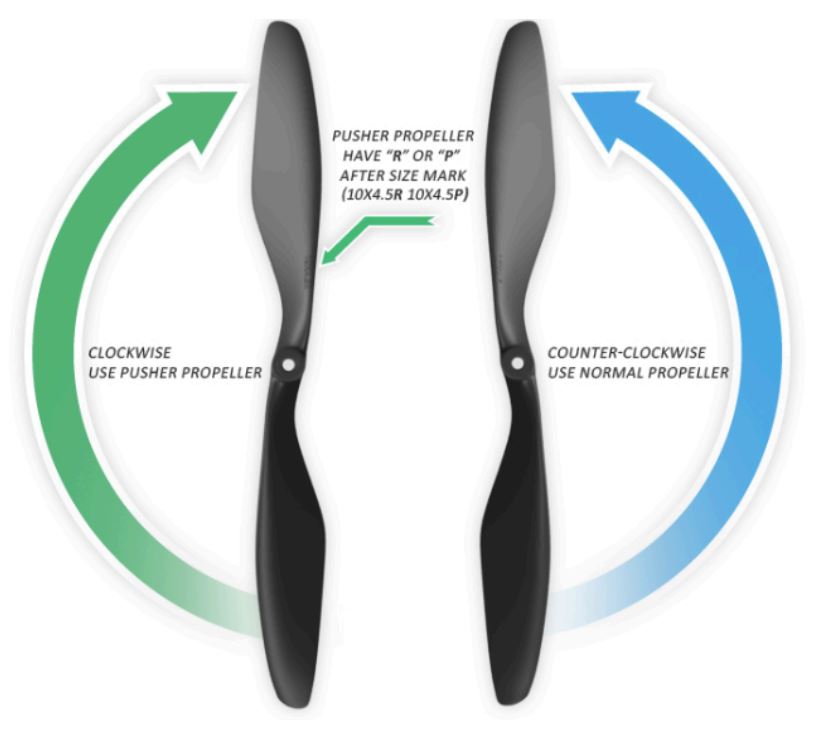
Attaching the propellers to your arducopter frame
  |
|
We hope that you enjoy fling your Arducopter Hexa Frame, if you have any questions please feel free to ask below.
 RSS Feed