
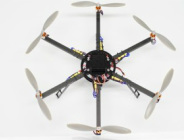
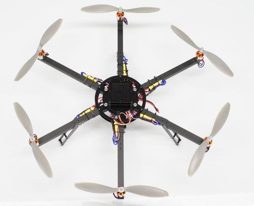
This Hexa frame is based off the Arducopter 3DR Quadcopter, but includes 2 extra motors for added lift and stability in windy conditions. This guide will show you how to assemble the kit
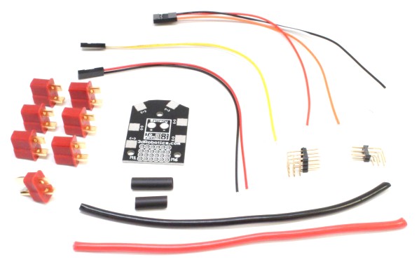
Arducopter Hexa Power Distribution Board Assembly
The Hexacopter power distribution board arrives as shown in the image above. To begin assembly, start by laying out the six female dean’s connectors in the appropriate spots around the PDB. They will be soldered at an angle so each lead makes contact with the pads on opposite sides of the board. Make sure you’re matching up the right pads by laying them all out before you start soldering. There should be exactly enough pads for the six connectors. Be careful to match up the positive and negative contacts properly as well. The connectors have raised lettering on the back that shows which tap is which.
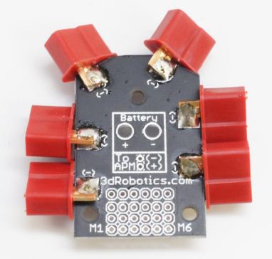 Connect both sides with a good amount of solder. | When you are sure of the proper positions, solder each connector in one by one. One technique that helps if you don’t have three hands is to orient the connector then superglue it in place before soldering, making sure not to superglue over the pads or metal tabs. 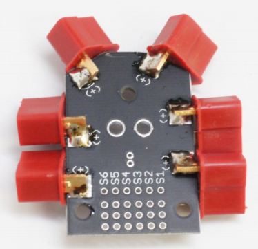 |
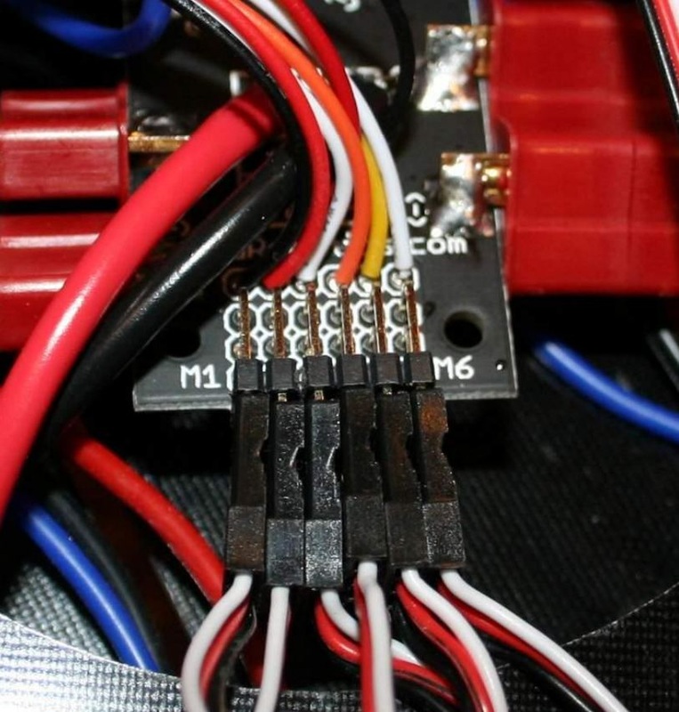
| Next insert the 4-wire cable into the holes shown above taking special care to do it in the right order. It should be Orange, White, Red then Black for motors 1-4 respectively.Solder the wires in from the back side. 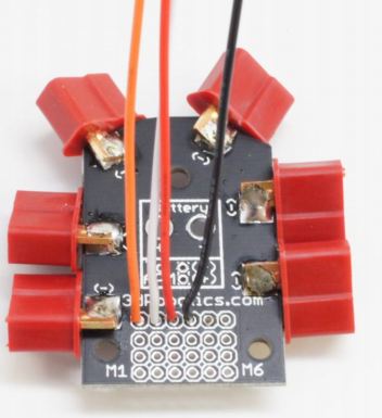 | 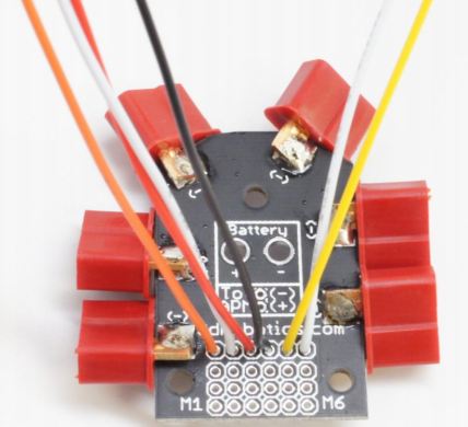 Next solder in the two wire connector, wires Yellow and White for motors 5 and 6 respectively |
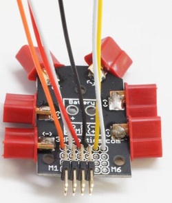
Now attach the 3x4 right angle headers to the holes at the edge of the board.
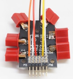
Then add in the 2x3 pin right angle header next to it.
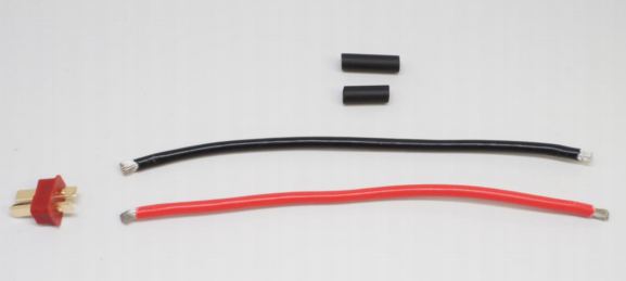 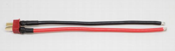 | Now take the 10AWG wire and strip both ends about 0.2 inches or 5mm. Then solder the wires to the tabs on the back of the male Dean’s connector. Make sure again to wire the red wire to the + tab and the black wire to the – tab. Slip the heatshrink on the back and heat it to cover the solder joints. |
| Now solder the loose ends of the 10AWG wire into the large holes on the board marked “+” and “-“. 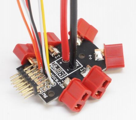 Finally solder in the small two-wire cable into the small holes marked “To APM” “+” and “-“, again with the red wire into “+” and the black wire into “-“. | 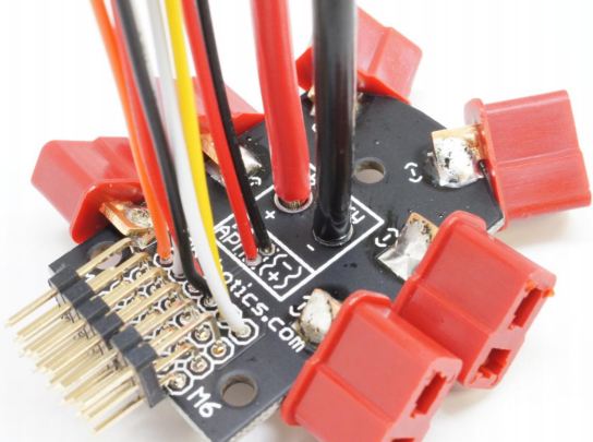 That’s it, your Power Distribution Board (PDB for short) is now complete! |
Hexacopter Center Plates
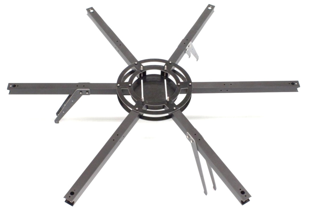
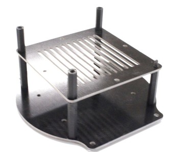
To begin assembling the Hexa 3DR frame, first get out the two parts pictured below. The piece on the left is the top half of the main frame and the piece on the right is the bottom
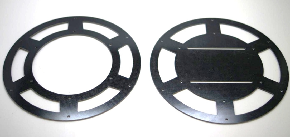
Lay them out in the same orientation shown above, we’ll start by adding the front and back arms.
Attaching arms to the main frame pieces
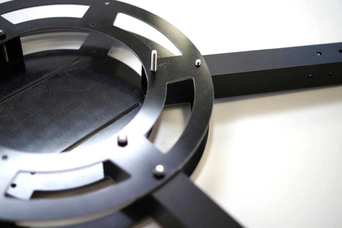
Take an arm and line it up with the holes on the main frame pieces as shown below. Do the front and the back arms first as the other four arms use different hardware. Make sure the arm is facing up as well, there should be motor mounting holes facing up at the other end of the arm when it’s inserted as below.
Insert two M3x25mm (only four metal screw sizes are included, 5, 22, 25 and 35 mm) screws from the bottom and fasten them on top with an M3 nut (color of the nut may vary but there’s only one size nut included in the kit).
Do the same with the opposite side
Now insert one of the side arms. This time use a M3x25mm screw for the outer hole and use a M3x35mm screw for the inner hole. The longer screw is used to attach the removable stackup later on.
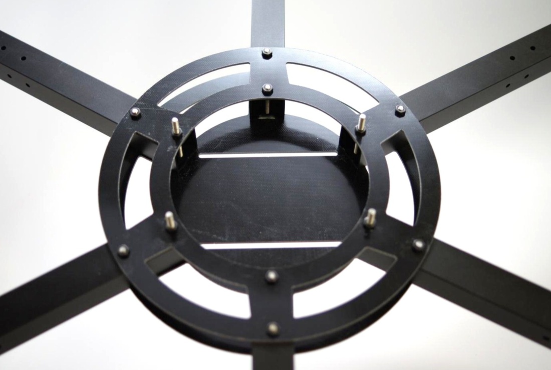
When you’re finished adding all the arms, the center should look like this. Double check that all arms are oriented correctly with the motor mounting holes facing up.
Attaching the landing legs onto the hexacopter arms
Now pull out two leg pieces and line them up with the holes on the side of the front arm. Fasten them with M3x25mm screws and M3 nuts.
 |  |
Then add a leg set to the two arms adjacent to the rear arm. When it’s finished, the legs should be installed like in the picture below, evenly spaced with one leg mounted facing directly forward (left in the picture below).
Next, take out 6 18mm plastic female-female spacers and 12 M3x5mm metal screws. Install them on each leg as shown below. This point doesn’t need to be very tight so don’t use too much force.
 |  |
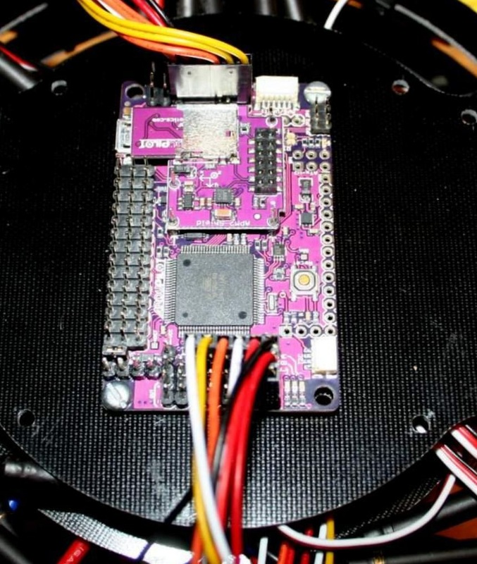
Mounting arducopter electronics
Once you’ve assembled your frame, mount the APM 2 board. It’s best to attach it with some double-sided foam tape to provide a bit of insulation and a solid base, then screw in a couple bolts in the mounting holes to keep in from moving.
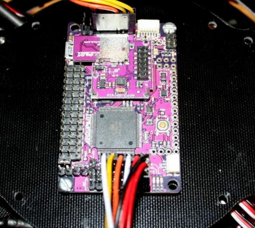
| Although it doesn’t matter what direction “front” is on a hexa frame, once you decide which direction the APM 2 board will face, that becomes front. The board orientation is shown the the right: You’ll note that the mounting holes on the 3DR Hexa default to a “+” configuration, which is to say that the board is facing one of the arms, rather than between two arms (known as an “x” configuration). You can mount it in an x configuration with double-sided tape if you want, but you’ll have to drill different mounting holes. We’ll assume you’re going to stick with the default + configuration for the rest of these instructions. It’s a good idea to mark your front arm with some red tape, so you can see the orientation of your copter in the air. | 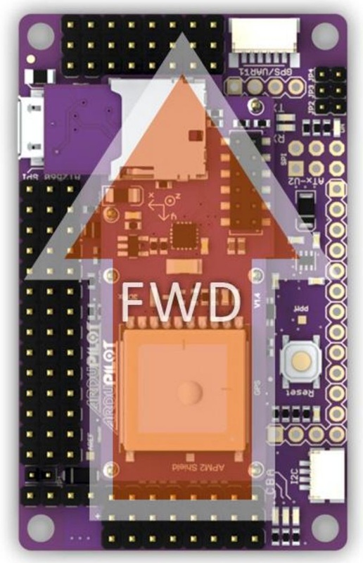 |
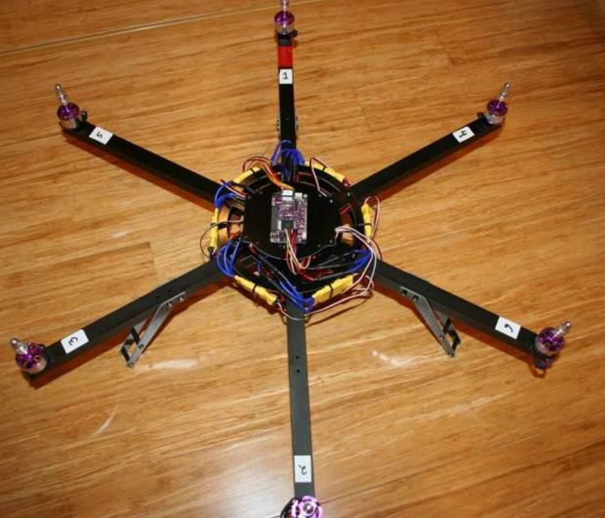
Now, let’s temporarily mark each arm with the motor number assigned by the ArduCopter code for the hexa configuration, which I’ve done in the picture below (for a Hexa + configuration). You can also see the red tape on the front arm:
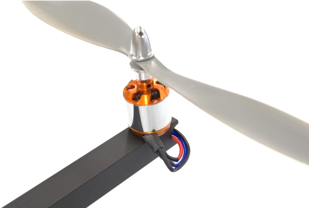
Now we’ll begin attaching the electronics. First, attach your motors to the end of each arm using the M3x22mm metal screws and included washers. If you have the UT 880kV motors as shown below, you will need to modify the aluminum arms a bit. The central hole needs to be slightly wider so it doesn’t restrict the movement of the black metal clip on the bottom of the motor. The easiest way is to use a drill with a bit slightly wider than that hole or a metal file would work as well. Increasing the hole diameter by about 1mm is enough. Then feed the three wires through the center of the arm and retrieve them on the other side.
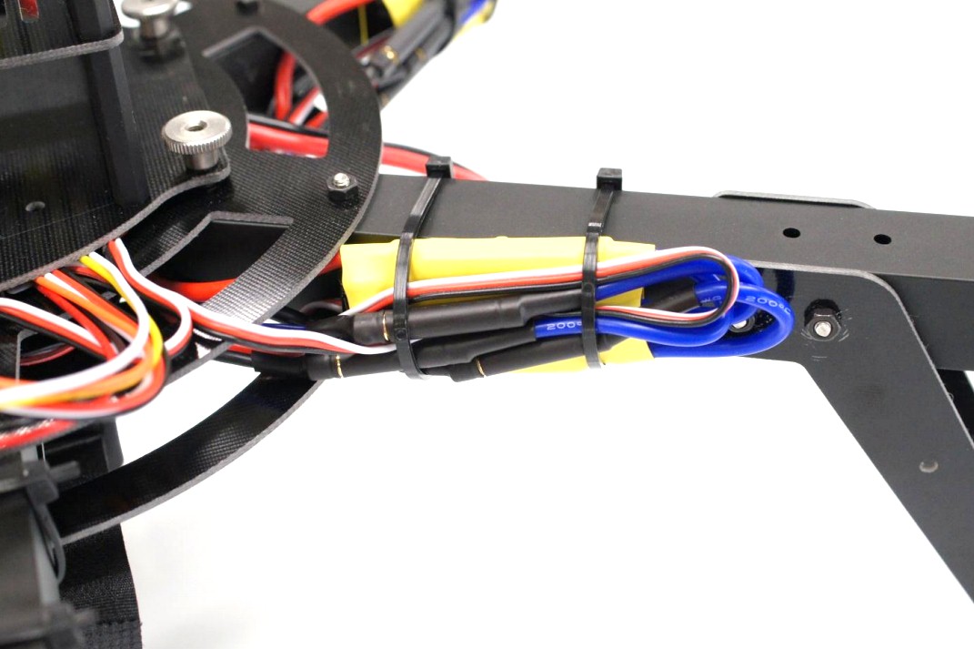
Plug the wires into an ESC and use a servo tester and battery to verify that the motor is spinning in the correct direction. Refer to the page - Arducopter Quickstart for which motors spin which direction. When the direction is confirmed, use zip ties to fasten the ESC to the arm as shown below. Try to get the ESC as flush to the arm as possible to assist in heat dissipation.
Once all the ESCs are plugged into their respective motors and attached, plug each of their signal wires into the back of the PDB as shown below. Start by plugging in the ESC attached to Motor 1 into the leftmost position and proceed through the rest to Motor 6.
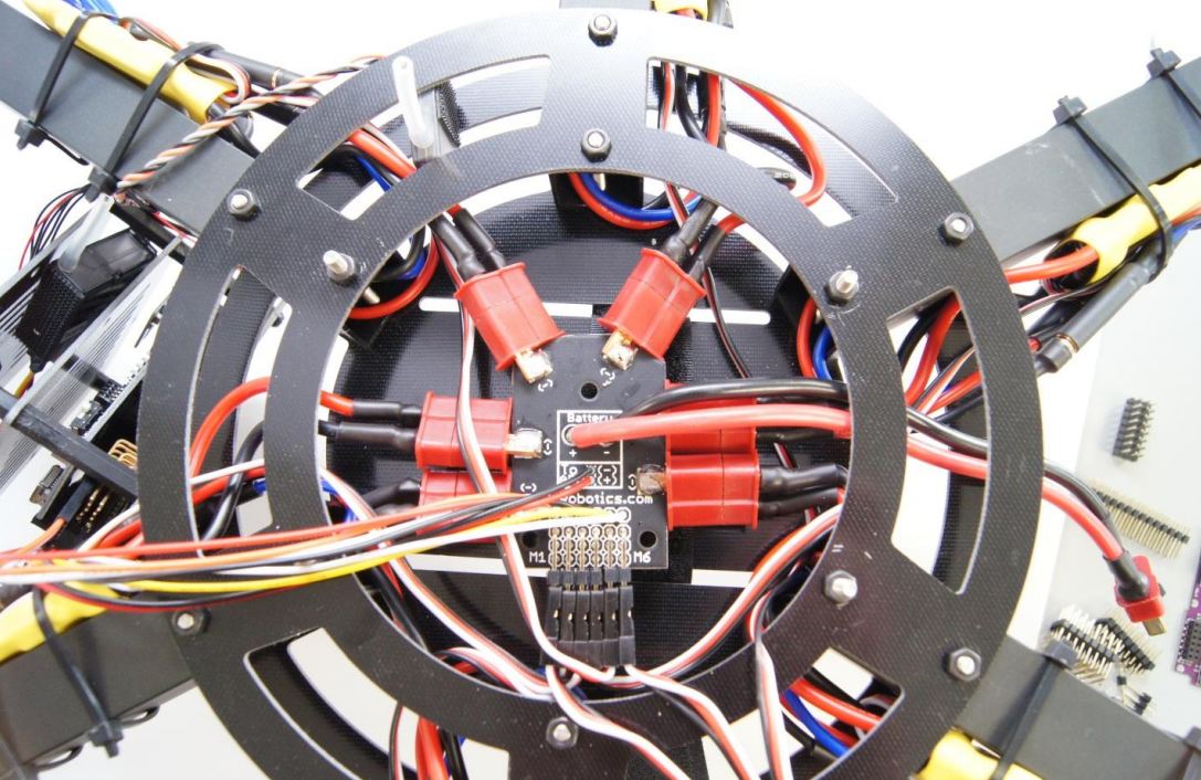
Then place your power distribution board (PDB) in the gap between the main plates and connect all the Deans connectors to the ESCs. It doesn’t matter which connector goes to which ESC as they’re all just connected to battery power
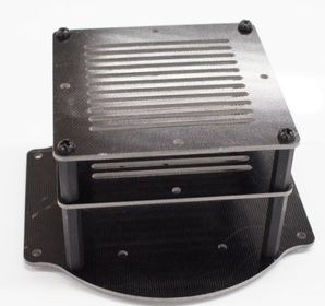
Stackup Assembly for your Arducopter Hexa frame
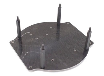
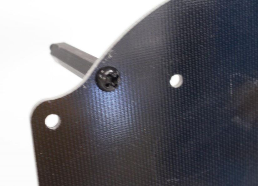
Next add the rest of the stackup layers. Start by fastening 4 M3x30mm Spacers into the base plate with 4 M3x5mm screws.
 |  |
Add a stackup board on top of the M3x30mm spacers then screw on 4 18mm female-female spacers.
Add another stackup board on top of that and then screw in 4 M3x5mm plastic screws into the spacers through the stackup.
Before mounting the stackup, put rubber washers onto the four longer screws on the main frame.
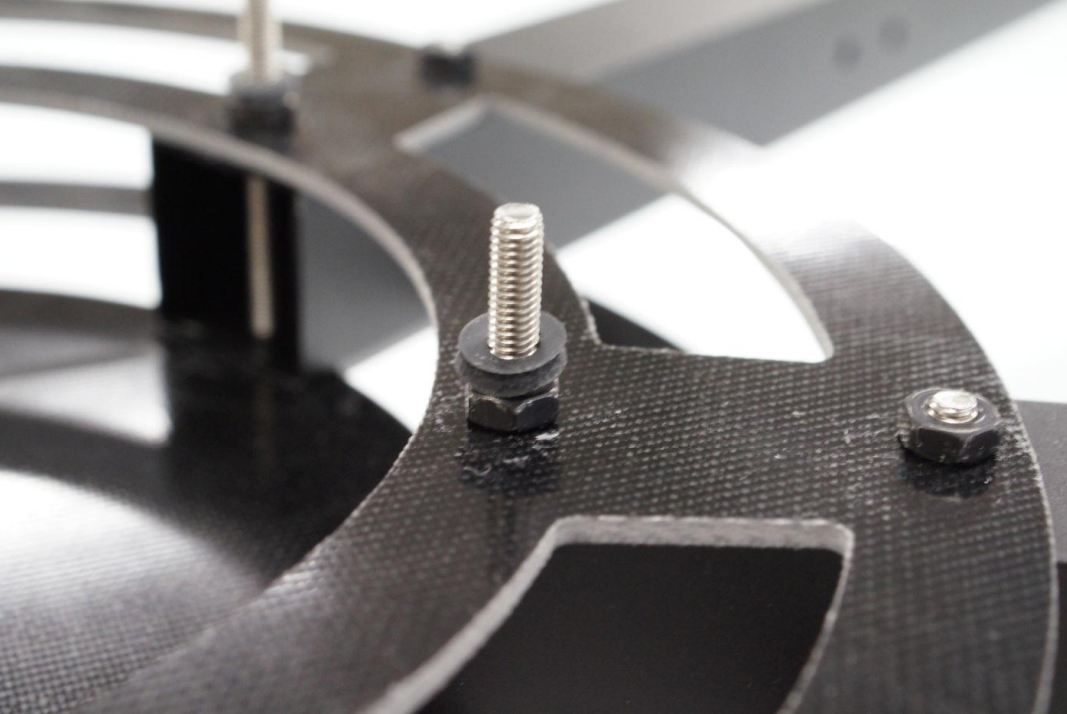
Finally, slide the stackup onto the main frame and screw it down using 4 thumb nuts. Be sure you’ve oriented it in the right direction so APM is facing forward.Then take the 4-pin connector and the two 2-pin connectors from the PDB and match them up to the RC outputs for each motor. The red and black cable should plug into the ground and power pin of RC Output 1 on APM.
Thats it, the last step is to connect your RC receiver and battery. For more information please refer the the arducopter quickstart guide.
We hope you enjoy your Arducopter Hexa Frame. If you have any questions please feel free to ask a question below or on the forums!
 RSS Feed